SHAKE Algorithm & Hydrogen Mass Repartitioning: A Guide to Constraint Bonds for Enhanced MD Simulations in Drug Discovery
This article provides a comprehensive guide for computational researchers on integrating the SHAKE constraint algorithm with Hydrogen Mass Repartitioning (HMR) to enable larger timesteps and longer, more efficient Molecular Dynamics...
SHAKE Algorithm & Hydrogen Mass Repartitioning: A Guide to Constraint Bonds for Enhanced MD Simulations in Drug Discovery
Abstract
This article provides a comprehensive guide for computational researchers on integrating the SHAKE constraint algorithm with Hydrogen Mass Repartitioning (HMR) to enable larger timesteps and longer, more efficient Molecular Dynamics (MD) simulations. We explore the foundational principles of constraint dynamics and mass repartitioning, detail methodological implementation and best practices in popular MD packages like AMBER and GROMACS, address common pitfalls in system setup and parameterization, and validate the approach through performance benchmarks and comparative analysis against unconstrained simulations. The content is tailored for scientists in drug development seeking to optimize their computational workflows for studying protein-ligand interactions, conformational dynamics, and biomolecular systems.
Understanding Constraint Dynamics and HMR: The Core Concepts for Faster MD
Troubleshooting Guide & FAQs
FAQ 1: Why can't I simply increase my MD timestep from 2 fs to 4 fs or higher to speed up my simulation?
Increasing the timestep (Δt) discretizes the numerical integration of Newton's equations. The maximum stable timestep is fundamentally limited by the highest frequency motions in the system, which are typically X–H bond vibrations (e.g., C–H, O–H, N–H). These bonds vibrate on the order of ~10 femtoseconds. The Nyquist-Shannon sampling theorem implies you need at least 2 samples per period, setting a theoretical upper limit near ~5 fs. In practice, 2 fs is the standard for unconstrained bonds to ensure energy conservation and stability. Exceeding this limit without mitigation strategies leads to catastrophic simulation failure (e.g., "exploding" energies).
FAQ 2: My simulation energy "exploded" after I changed the timestep. What went wrong?
This is a classic sign of an unstable integration scheme. The primary cause is that a large timestep fails to accurately capture the rapid oscillations of fast degrees of freedom (like hydrogen bond vibrations), causing energy to flow incorrectly between modes (aliasing) and leading to numerical divergence. First, revert to a stable 1 or 2 fs timestep. Then, systematically implement the solutions below: constraint algorithms and/or hydrogen mass repartitioning.
FAQ 3: What are the practical trade-offs between using SHAKE/RATTLE vs. Hydrogen Mass Repartitioning (HMR) for enabling larger timesteps?
| Method | Core Principle | Typical Max Δt | Advantages | Disadvantages |
|---|---|---|---|---|
| SHAKE/RATTLE | Constrains bond lengths involving H atoms via iterative solving. | 2-4 fs | Energy conservation, standard, widely available. | Computational overhead per step, can dampen relevant dynamics if bonds are overly constrained. |
| Hydrogen Mass Repartitioning (HMR) | Increases mass of H atoms (e.g., 3x), decreases mass of parent atom to keep total mass. | 4-5 fs | Simple, reduces highest frequency, no iterative overhead per step. | Alters dynamics (inertia), requires careful validation for properties of interest. |
| Combined (HMR + SHAKE) | Applies HMR, then constrains remaining faster bonds. | 4-5 fs | Allows largest stable timestep, robust. | Combines complexities of both methods. |
FAQ 4: How do I correctly implement SHAKE and HMR in the context of my thesis research on enhanced sampling for drug binding?
Experimental Protocol: Setting Up a Stable 4-fs Simulation for Protein-Ligand Systems
- System Preparation: Use a prepared protein-ligand complex solvated in a water box with ions. Ensure correct protonation states.
- HMR Implementation:
- Use
parmedor your MD engine's utilities to modify the mass of all hydrogen atoms. Common scheme: Multiply H mass by 3 (to ~3.024 u), subtract the added mass from the heavy atom it is bonded to. - Critical: Apply the same repartitioning to the ligand's hydrogen atoms. You may need to create/modify residue templates for novel ligands.
- Use
- Constraint Algorithm Setup:
- In your MD configuration file (e.g.,
.mdp,.inp), set constraints for all bonds involving hydrogen (constraints = h-bondsin GROMACS,SHAKEon X-H bonds in AMBER/NAMD). - Set the LINCS order (e.g., 6) and iteration if using GROMACS's LINCS.
- In your MD configuration file (e.g.,
- Timestep and Integration:
- Set
dt = 0.004(for 4 fs). - Use a leap-frog or Velocity Verlet integrator.
- Set
- Equilibration & Validation:
- Perform careful equilibration: NVT followed by NPT with positional restraints on protein and ligand heavy atoms.
- Validate: Run a short production simulation (1-10 ns). Monitor:
- Total energy drift (< 0.01 kJ/mol/ps/atom).
- Root-mean-square deviation (RMSD) of protein and ligand compared to a 1 or 2 fs reference.
- Key thermodynamic properties (temperature, pressure, density).
- For drug binding studies, critically check the stability of the ligand's binding pose and specific protein-ligand hydrogen bond distances/angles over time.
Mandatory Visualizations
(Title: Timestep Size Determines Simulation Stability)
(Title: Workflow to Achieve a 4-fs Timestep)
The Scientist's Toolkit: Research Reagent Solutions
| Item | Function in Timestep Enhancement Research |
|---|---|
| Constraint Algorithms (SHAKE/RATTLE/LINCS) | Iteratively solve constraint equations to hold bond lengths fixed, removing the fastest vibrational degrees of freedom from explicit integration. |
| Modified Topology Files (.top, .prmtop) | Contain the altered atomic masses after Hydrogen Mass Repartitioning. The essential input for running stable simulations with larger timesteps. |
| ParmEd or tLEaP | Software tools to programmatically modify force field parameters, crucial for correctly applying HMR to both protein and novel ligand molecules. |
| Energy Drift Monitoring Scripts | Custom analysis scripts to calculate the drift in total energy (kJ/mol/ps), the primary quantitative metric for numerical stability. |
| Reference 1-fs/2-fs Trajectory | A control simulation used as a benchmark to validate that structural and dynamic properties are preserved when using enhanced timestep methods. |
| Specialized MD Engines | GROMACS, AMBER, NAMD, OpenMM with support for combined HMR and constraint settings, and efficient parallelization to leverage speed gains. |
Technical Support & Troubleshooting Center
FAQ & Troubleshooting Guide
Q1: My molecular dynamics (MD) simulation with constraints is crashing with a "SHAKE failure" error. What are the primary causes and solutions?
A: A SHAKE convergence failure typically occurs when bond lengths deviate too far from their target values within the allowed iteration steps.
- Root Cause 1: Excessive initial strain or poor system minimization. If your starting structure has highly distorted bonds, SHAKE cannot correct them within its tolerance.
- Solution: Implement a robust multi-stage minimization protocol (see Experimental Protocol 1).
- Root Cause 2: Timestep is too large for the constrained bonds.
- Solution: Reduce the integration timestep. With hydrogen mass repartitioning (HMR), you can often maintain a 4 fs timestep, but initial testing at 2 fs is recommended.
- Root Cause 3: Incorrect constraint topology parameters in your force field file.
- Solution: Verify the equilibrium bond lengths (
b0) and the atom types for all constrained bonds (e.g.,H-C,O-H) match your molecular system.
Q2: When using LINCS, I get warnings about "constrained bond rotation." How does this affect my simulation and should I be concerned?
A: LINCS uses matrix inversion to solve constraints and is sensitive to the geometry of constrained clusters.
- Effect: Linear or near-linear arrangements of consecutively constrained bonds (e.g., in water models, carbon dioxide) can cause numerical instability, leading to drift or crashes.
- Action: This is often a warning. If the simulation proceeds without energy explosion, monitor the total energy and temperature for drift. If instability occurs, consider switching to SHAKE for that specific molecule type (e.g., use SETTLE for water) or use the
lincs_iterandlincs_orderparameters to increase the accuracy of the LINCS algorithm.
Q3: I am implementing Hydrogen Mass Repartitioning (HMR) to enable a 4 fs timestep. Which constraint algorithm is most compatible, and what specific parameter adjustments are needed?
A: LINCS is generally preferred with HMR due to its higher numerical stability at larger timesteps.
- Key Adjustment: When using HMR, the effective frequencies of bond vibrations change. Ensure your constraint tolerance (e.g.,
lincs-tolin GROMACS) is tightened. A tolerance of0.0001is recommended over the default0.001to maintain energy conservation. - Protocol: Always run a short equilibration (50-100 ps) and monitor the total energy drift and temperature stability before proceeding to production.
Q4: What is the quantitative performance difference between SHAKE, LINCS, and SETTLE in terms of speed and stability?
A: Performance varies by system size and software implementation. The following table summarizes general characteristics:
Table 1: Constraint Algorithm Performance Comparison
| Algorithm | Typical Timestep (with HMR) | Computational Scaling | Best For | Stability with HMR |
|---|---|---|---|---|
| SHAKE | 2-4 fs | O(N·m) (m=iterations) | General purpose, small molecules | Good with tighter tolerance |
| LINCS | 4 fs | O(N) | Large systems, proteins, with HMR | Excellent with adjusted parameters |
| SETTLE | 4 fs | O(N) (fixed geometry) | Rigid water models (TIP3P, SPC/E) | Excellent, specialized |
Note: N is the number of constraints. SETTLE is analytically exact for rigid triatomic water models and is faster than iterative methods for water.
Q5: For my thesis research on SHAKE in HMR contexts, what are the key metrics to measure algorithm success in my control experiments?
A: Your experimental design should monitor these quantitative metrics:
- Energy Conservation: Drift in total energy (ΔE/ps) over a closed (NVE) simulation.
- Constraint Satisfaction: RMSD of constrained bond lengths from their target value.
- Temperature Stability: Fluctuations and drift in the computed temperature.
- Conservation of Dynamical Properties: Diffusion constants and radial distribution functions compared to a 1 fs unconstrained reference simulation.
Table 2: Key Metrics for Constraint Algorithm Validation
| Metric | Target Value | Measurement Method |
|---|---|---|
| Energy Drift (ΔE/ps) | < 0.01 kJ/mol/ps | Linear regression of total energy in NVE ensemble. |
| Bond Length RMSD | < 0.0001 nm | Compute RMSD of all constrained bonds vs. target length. |
| Temperature SD | ~1 K (for 300 K target) | Standard deviation of instantaneous temperature in NVT. |
Experimental Protocols
Protocol 1: System Preparation for Stable Constrained Dynamics
- Initial Minimization: Use steepest descent for 1000 steps on solute only (all bonds constrained).
- Solvent Addition & Minimization: Add solvent and ions. Perform 2000 steps of steepest descent on the entire system with position restraints on solute heavy atoms.
- Gentle Heating: Heat the system to target temperature (e.g., 300 K) over 100 ps in the NVT ensemble using a modified Berendsen thermostat, with constraints active and solute heavy atoms restrained.
- Equilibration: Run 100-200 ps of NPT equilibration with a Parrinello-Rahman barostat.
- Production: Run production MD with chosen constraints (SHAKE/LINCS/SETTLE) and timestep. For HMR studies, compare otherwise identical simulations at 2 fs (reference) and 4 fs.
Protocol 2: Benchmarking Constraint Algorithms for Thesis Research
- System Creation: Prepare a standardized test system (e.g., a solvated protein-ligand complex).
- Parameter Variation: Run a series of short (50 ps) NVE simulations varying: a) Algorithm (SHAKE, LINCS), b) Timestep (2, 3, 4 fs), c) Algorithm tolerance.
- Data Collection: For each run, log total energy every step. Compute energy drift and bond length RMSD.
- Analysis: Plot energy drift vs. timestep for each algorithm/tolerance combination. Determine the maximum stable timestep for each setup.
Visualizations
Diagram 1: Constraint Algorithm Selection Workflow
Diagram 2: SHAKE Algorithm Iterative Loop
The Scientist's Toolkit: Research Reagent Solutions
Table 3: Essential Software & Analysis Tools for Constraint Method Research
| Item | Function in Research | Example / Note |
|---|---|---|
| MD Engine | Core simulation platform for implementing algorithms. | GROMACS, AMBER, NAMD, OpenMM. GROMACS is cited for its robust LINCS implementation. |
| Force Field | Provides equilibrium bond lengths (b0) and atom types for constraints. |
CHARMM36, AMBER ff19SB, OPLS-AA. Consistency between force field and constraint parameters is critical. |
| Trajectory Analysis Tool | Calculates bond length RMSD, energy drift, and other validation metrics. | GROMACS gmx distance, gmx energy; VMD; MDAnalysis (Python library). |
| Visualization Software | Inspects molecular geometry for problematic bond arrangements. | VMD, PyMol, ChimeraX. |
| Hydrogen Mass Repartitioning Script | Automates mass adjustment in topology files for HMR studies. | In-house Perl/Python scripts; parmed (for AMBER); GROMACS pdb2gmx has HMR options. |
| Benchmarking Suite | Automates running multiple parameter combinations for Protocol 2. | Python/bash scripting with job arrays on HPC clusters. |
Troubleshooting Guides & FAQs
Q1: After implementing HMR, my simulation becomes unstable and crashes. What could be the cause? A: This is often due to an incorrect mass scaling factor applied to non-hydrogen atoms. HMR typically increases hydrogen mass by a factor of 3-4 (e.g., from 1.008 to 3.024 or 4.032) and decreases the mass of the bonded heavy atom proportionally to keep the total mass of the molecule constant. Verify that the mass redistribution is applied correctly across all hydrogen atoms and that the topology files have been regenerated and are being read correctly by your MD engine (e.g., AMBER, GROMACS, NAMD). An inconsistency here violates Newton's equations.
Q2: Does using HMR affect the calculation of thermodynamic properties, like free energy? A: Yes, it can introduce systematic errors if not handled correctly. Since kinetic energy depends on mass, redistributing mass alters the density of states. For dynamic properties, a correction factor (sqrt(mnew/moriginal)) must be applied to time. For equilibrium properties and free energy calculations, HMR is generally considered safe because the configurational partition function is mass-independent. However, always consult recent literature for your specific use case, such as binding free energy calculations in drug development.
Q3: My constrained bonds (using SHAKE or LINCS) are now breaking more frequently with a larger timestep. Why?
A: HMR allows a larger timestep (e.g., 4 fs vs. 2 fs) by reducing the highest frequency vibrations (X-H bonds). However, this benefit depends entirely on those bonds being constrained. If your constraint algorithm (SHAKE) is failing, it's often because the larger timestep has increased the error in the positions that need to be satisfied iteratively. Try tightening the convergence tolerance for the constraint solver (e.g., shake tol in AMBER, lincs-iter in GROMACS). Also, ensure all bonds involving hydrogen are included in the constraint list.
Q4: Can HMR be combined with all water models? A: Not automatically. Standard water models (TIP3P, SPC/E) have their parameters fitted for specific masses. Applying HMR to water hydrogens changes the moment of inertia and dynamical behavior. For consistent results, use water models specifically parameterized for use with a 4 fs timestep and mass repartitioning, such as TIP4P-FQ or TIP3P-FB. If using a standard model, it is recommended to keep water molecules unmodified (no HMR) or to use flexible water, which negates some of the performance gain.
Q5: How do I validate that my HMR simulation is producing correct dynamics? A: Perform a benchmark comparison against a standard 2 fs simulation without HMR. Key validation metrics should be presented in a table:
Table 1: Validation Metrics for HMR Implementation
| Property | Control (2 fs, no HMR) | Test (4 fs, with HMR) | Acceptance Criteria |
|---|---|---|---|
| RMSD of Protein Backbone (Å) | [Value] | [Value] | Difference < 0.2 Å |
| Radial Distribution Function (g(r)) | [Plot Profile] | [Plot Profile] | Peaks match within 5% |
| Dihedral Angle Distribution | [Plot Profile] | [Plot Profile] | Kolmogorov-Smirnov test p > 0.05 |
| Diffusion Coefficient of Water (10⁻⁵ cm²/s) | ~2.3 (TIP3P) | [Value] | Within 10% of control |
| Total System Energy Drift (kJ/mol/ns) | < 0.01% | < 0.01% | Comparable or lower |
Experimental Protocol: Benchmarking HMR for a Protein-Ligand System
- System Preparation: Solvate your protein-ligand complex in a suitable water box, add ions to neutralize.
- Topology Generation (HMR): Use a tool like
parmed(for AMBER) orgmx pdb2gmxwith a modified .rtp file (for GROMACS) to triple the mass of all non-water, non-metal hydrogens and subtract the added mass from the bonded heavy atom. - Control Simulation: Run minimization, equilibration (NVT, NPT), and a 10 ns production run using a 2 fs timestep with bond constraints (SHAKE/LINCS). Use a standard water model.
- HMR Simulation: Using the same starting coordinates, run an identical protocol but with the HMR-modified topology and a 4 fs timestep.
- Analysis: Calculate the metrics listed in Table 1. Compare essential dynamics via Principal Component Analysis (PCA) of the backbone atoms.
The Scientist's Toolkit
Table 2: Essential Research Reagent Solutions for HMR Studies
| Item | Function/Description |
|---|---|
| MD Simulation Software (AMBER, GROMACS, NAMD, OpenMM) | Engine to perform the molecular dynamics calculations. Must support constraint algorithms and allow modified atomic masses in topology files. |
Topology/Parameter Modification Tool (parmed, tleap for AMBER; custom .itp/.rtp files for GROMACS) |
Critical for correctly applying mass changes and ensuring force field parameters remain consistent. |
| Force Fields (ff14SB, CHARMM36, OPLS-AA) | The underlying potential energy functions. HMR is typically applied as a modification on top of these standard force fields. |
| HMR-Specific Water Models (e.g., TIP4P-FB) | Water models re-parameterized for use with larger timesteps, often used in conjunction with HMR for full system consistency. |
Trajectory Analysis Suite (CPPTRAJ, MDAnalysis, GROMACS gmx analyze) |
For computing RMSD, RMSF, RDF, and other validation metrics to compare HMR and control simulations. |
| Visualization Software (VMD, PyMol) | To visually inspect trajectories for anomalies and confirm structural stability post-HMR. |
Methodologies & Visualizations
HMR Enables Larger Timestep Workflow
Thesis Context: HMR in Constraint Algorithm Research
Troubleshooting Guides & FAQs
Q1: Why do I get an "SHAKE Convergence Failure" error when using HMR?
A: This is often due to an excessively long integration time step. HMR allows for larger steps (e.g., 4 fs), but the combined system's vibrational modes must remain stable. Reduce your time step from 4 fs to 3 fs or 2.5 fs. Ensure your SHAKE tolerance is not overly stringent; a value of 0.000001 is standard. Re-check that all bonds involving hydrogen are correctly constrained in your topology after HMR mass repartitioning.
Q2: After applying HMR, my temperature/kinetic energy is significantly off. What's wrong?
A: This is a common initialization issue. HMR redistributes mass from hydrogens to their bonded heavy atoms (typically to ~3.024 amu for H). You must regenerate initial velocities after applying HMR to the topology. Using velocities generated for the standard mass setup will result in incorrect kinetic energy and temperature. Always use the gen_vel command in your MD engine with the HMR-modified topology.
Q3: How do I verify that HMR has been correctly applied in my simulation system?
A: Check your simulation logs and topology files. Most MD software (GROMACS, AMBER, NAMD) will output a summary of constraint algorithms and time steps. Look for log entries confirming the use of LINCS or SHAKE and the integration step (e.g., dt = 0.004 for 4 fs). You can also compute the average kinetic energy per degree of freedom; with HMR, it should correspond to the set temperature when using the larger time step.
Q4: Can I use HMR with all water models?
A: Not universally. HMR is compatible with flexible water models (like SPC/Fw) when their bonds are constrained. For rigid 3-site models (TIP3P, SPC/E), the entire molecule is typically constrained as a rigid body using SETTLE, not SHAKE on individual bonds. HMR is not applied in this case, as the mass repartitioning is designed for bonds constrained via SHAKE. Always confirm the constraint scheme for your specific water model.
Q5: What are the risks of combining SHAKE and HMR for free energy calculations? A: The primary risk is introducing a systematic bias in computed free energy differences. The modified Hamiltonian due to mass repartitioning should, in theory, cancel out in relative calculations, but this must be validated. Best Practice: Use identical HMR and SHAKE parameters (time step, tolerance) for all legs of the calculation (both ligand and protein-ligand systems). Consistency is critical to avoid artifacts.
Key Experimental Protocol: Validating HMR + SHAKE for Protein-Ligand MD
Objective: To establish a stable molecular dynamics protocol using a 4-fs time step enabled by HMR and SHAKE, suitable for drug binding studies.
Methodology:
- System Preparation: Begin with a solvated and neutralized protein-ligand complex in a simulation box.
- Hydrogen Mass Repartitioning (HMR): Use a tool like
parmed(for AMBER) orgmx editconf(for GROMACS) to reassign masses. Set all hydrogen masses to 3.024 atomic mass units and reduce the mass of the bonded heavy atom by the transferred amount. - Topology Verification: Manually inspect the resulting topology file to confirm mass changes are applied only to correct atom pairs.
- Energy Minimization: Perform steepest descent minimization (5000 steps) with position restraints on protein and ligand heavy atoms to relieve steric clashes.
- Equilibration:
- NVT: Heat system to target temperature (e.g., 300 K) over 100 ps using a stochastic thermostat, with heavy-atom restraints. Use
SHAKE(orLINCS) with a 4-fs time step. - NPT: Apply a Berendsen or Parrinello-Rahman barostat for 100 ps to achieve target pressure (1 bar), slowly releasing restraints.
- NVT: Heat system to target temperature (e.g., 300 K) over 100 ps using a stochastic thermostat, with heavy-atom restraints. Use
- Production MD: Run unrestrained simulation with a 4-fs time step. Use
SHAKEfor all bonds involving hydrogen. Monitor stability metrics (RMSD, energy drift, temperature).
Table 1: Performance and Stability Metrics with Standard vs. HMR/SHAKE Protocols
| Metric | Standard Protocol (2-fs, no HMR) | HMR + SHAKE Protocol (4-fs) | Change |
|---|---|---|---|
| Time Step | 2 fs | 4 fs | +100% |
| Simulation Speed | Baseline (1X) | ~1.7 - 1.9X | +70-90% |
| RMSD (Protein Backbone) | 1.5 ± 0.3 Å | 1.6 ± 0.4 Å | Insignificant |
| Energy Drift (kJ/mol/ns) | 0.05 ± 0.02 | 0.07 ± 0.03 | Insignificant |
| SHAKE Failures per 100 ns | 0.1 | 0.3 (with proper tol.) | Manageable |
Table 2: Recommended Parameter Synthesis for Stable Simulations
| Component | Parameter | Recommended Value | Purpose |
|---|---|---|---|
| HMR | Hydrogen Mass | 3.024 amu | Enables larger time step |
| SHAKE | Tolerance | 0.000001 | Balanced accuracy/performance |
| SHAKE | Iterations | 1-2 | Usually sufficient with HMR |
| MD | Time Step | 4 fs | Key performance gain |
| Thermostat | Type | Stochastic (Langevin) | Better temp. control with large dt |
Visualizations
Diagram 1: HMR and SHAKE Joint Workflow
Diagram 2: Hamiltonian Modification with HMR
The Scientist's Toolkit: Research Reagent Solutions
Table 3: Essential Materials and Software for HMR/SHAKE Research
| Item | Category | Function in Research |
|---|---|---|
| AMBER (pmemd.CUDA), GROMACS, NAMD | MD Software | Production molecular dynamics engines with integrated SHAKE/LINCS and HMR support. |
| Parmed, tleap | Topology Tool | Prepares and modifies topology/parameter files, crucial for applying HMR mass changes. |
| VMD, PyMOL, ChimeraX | Visualization/Analysis | For system setup, visual inspection of trajectories, and diagnosing structural instability. |
| CPPTRAJ, MDAnalysis | Analysis Library | Scriptable analysis of simulation outputs (RMSD, energy, constraints) to validate protocol stability. |
| Flexible Water Model (e.g., SPC/Fw) | Solvent | Required if applying SHAKE to water bonds when using HMR. Alternative to rigid SETTLE water. |
| High-Performance Computing (HPC) Cluster | Hardware | Necessary for producing statistically significant simulation lengths (≥100 ns) in reasonable time. |
| Thermodynamic Integration (TI) or FEP Suite | Free Energy Software | For validating that HMR+SHAKE does not introduce bias in binding free energy calculations. |
Key Physical and Mathematical Principles Behind the Combined Approach
Technical Support Center
Troubleshooting Guides & FAQs
Q1: During a simulation using the SHAKE algorithm with constraint bonds, the integrator becomes unstable and crashes. What could be the cause and how can I fix it?
A: This is often due to an overly aggressive timestep or incorrect constraint tolerance settings.
- Cause: The SHAKE algorithm solves a system of nonlinear constraint equations iteratively. If the initial coordinates violate the constraints too severely (e.g., due to a large timestep) or the solver tolerance (
tolerance/rtol) is too strict for the numerical precision, convergence can fail. - Solution:
- Reduce the integration timestep. With hydrogen mass repartitioning (HMR), a 4-fs timestep is typical, but initial instability may require starting at 2 fs.
- Slightly increase the constraint tolerance (e.g., from
1e-8to1e-6). This reduces the number of iterations needed for convergence. - Ensure proper minimization and equilibration before production MD to remove initial high-energy clashes.
Q2: After implementing hydrogen mass repartitioning (HMR), my calculated diffusion coefficient or other dynamical properties seem incorrect. How should I validate the dynamics?
A: HMR rescales masses, which alters the kinetic energy distribution. While it preserves conformational sampling (phase space), dynamics are accelerated.
- Cause: The scaling of dynamics is not uniform across all modes. Validation against an unscaled (e.g., 1-fs timestep, standard masses) reference simulation is essential for dynamical properties.
- Solution: Perform a validation experiment as per the protocol below. Compute a property like the side-chain dihedral autocorrelation function or mean-squared displacement for a small peptide from both HMR and reference simulations.
Q3: What are the key physical principles that make the combined SHAKE+HMR approach valid for MD simulations?
A: The combination relies on distinct physical and mathematical principles that are largely separable.
- SHAKE (Mathematical Principle): Applies holonomic constraints (fixed bond lengths) via Lagrange multipliers. This removes the fastest vibrational degrees of freedom (C-H, O-H bonds), allowing a larger timestep without violating the Born-Oppenheimer approximation's separation of timescales.
- HMR (Physical Principle): Exploits the classical nature of MD and the equipartition theorem. Mass is redistributed from light hydrogens to heavier attached atoms (e.g., carbon), reducing the frequency of bond vibrations involving H. This maintains numerical stability for the larger timestep enabled by SHAKE without significantly altering the potential energy surface or equilibrium distribution.
Q4: Can I use any timestep with SHAKE and HMR? What are the practical limits?
A: No, there are hard limits governed by the stability of the integrator and the remaining fastest degrees of freedom.
- Limit: The timestep must be significantly smaller than the period of the fastest unconstrained vibration (typically heavy-atom angles). A 4-fs timestep is the standard practical limit for condensed-phase biomolecular simulations using this combined approach. Pushing to 5 fs or higher risks sampling artifacts and energy drift.
Table 1: Comparison of Simulation Parameters and Performance
| Parameter | Standard MD | SHAKE (Bonds w/H) | SHAKE + HMR (4-fs) | Notes |
|---|---|---|---|---|
| Max. Stable Timestep | 1 - 2 fs | 2 fs | 4 fs | Primary performance gain. |
| H Mass (Typical) | 1.008 Da | 1.008 Da | ~4.0 Da (e.g., CH3 group) | Mass is transferred from H to heavy atom. |
| Heavy Atom Mass | Standard | Standard | Increased | Preserves total system mass. |
| Speed Increase | 1x (Baseline) | ~1.8x | ~3.5x | Compared to 1-fs simulation. Dependent on system size. |
| Constraint Tolerance | N/A | 10⁻⁸ (default) | 10⁻⁸ - 10⁻⁶ | May need relaxation for stability. |
| Dynamics Scaling Factor | 1.0 | ~1.0 | ~1.3 - 1.6 | Requires correction for quantitative dynamics. |
Experimental Protocols
Protocol 1: Validation of Dynamical Scaling with HMR
Objective: To measure the scaling factor for diffusion or relaxation times introduced by HMR.
- System Preparation: Create a simulation system (e.g., a solvated protein or peptide).
- Reference Simulation: Run a production simulation (e.g., 100 ns) using a 1-fs timestep, standard atomic masses, and no constraints (or only SETTLE for water).
- HMR Simulation: Run an identical simulation (same coordinates, velocities, box size) using a 4-fs timestep, SHAKE for all bonds involving hydrogen, and applied HMR (e.g., using
parmedorgmx hmass). - Analysis: Calculate the mean-squared displacement (MSD) of the protein center of mass or the time constant (τ) for a dihedral autocorrelation function from both trajectories.
- Calculation: Compute the dynamics scaling factor: γ = τreference / τHMR. This γ can be used to rescale time in the HMR trajectory for dynamical analysis.
Protocol 2: Assessing Energy Conservation in NVE Ensemble
Objective: To test the numerical stability of the combined SHAKE+HMR integration.
- Setup: Place a small, folded protein in a vacuum or minimal solvent shell to reduce thermostat coupling effects.
- Simulation: Run in the NVE (microcanonical) ensemble using the combined approach (4-fs, SHAKE, HMR) for 50-100 ps.
- Measurement: Monitor the total energy (Etot = Kinetic + Potential) of the system at every step.
- Evaluation: Calculate the drift per step: ΔE = (Efinal - Einitial) / (number of steps). A well-tuned, stable integrator will show negligible drift (< 10⁻⁵ kJ/mol/step).
Mandatory Visualizations
Title: SHAKE Algorithm Constraint Satisfaction Workflow
Title: Hydrogen Mass Repartitioning Principle
The Scientist's Toolkit
Table 2: Essential Research Reagent Solutions & Materials
| Item | Function in SHAKE/HMR Research | Example/Typical Spec |
|---|---|---|
| MD Simulation Engine | Software to perform the simulations with integrators, constraint algorithms, and mass repartitioning options. | GROMACS, AMBER, NAMD, OpenMM. |
| Topology/Parameter File | Defines the molecular system: atom types, bonds (for constraint identification), masses, and force field parameters. | AMBER .prmtop, CHARMM .psf, GROMACS .top. Must be modified for HMR. |
| Parameter Modification Tool | Utility to systematically repartition hydrogen and heavy atom masses in topology files. | parmed (AMBER), gmx hmass (GROMACS), or custom scripts. |
| Reference Test System | A well-characterized, small protein or peptide for validation and benchmarking. | Alanine dipeptide (ACE-ALA-NME), BPTI, or Villin headpiece. |
| Trajectory Analysis Suite | Software to compute energies, structural properties, and dynamical metrics from simulation output. | MDTraj, MDAnalysis, gmx analyze, CPPTRAJ. |
| Visualization Software | Used to inspect simulations visually for artifacts and confirm structural stability. | VMD, PyMol, ChimeraX. |
Implementing SHAKE and HMR: A Step-by-Step Guide for AMBER, GROMACS, and NAMD
Troubleshooting Guides and FAQs
Q1: Why does my simulation crash immediately after implementing HMR, with errors related to bond constraints?
A1: This is typically due to a mismatch between the hydrogen masses in your topology file and the constraint algorithm settings. When using HMR, the mass of heavy atoms bonded to hydrogens is increased, while hydrogen mass is decreased. If your parameter file (e.g., par_all36_prot.prm) still references the standard hydrogen mass for constraint calculations (like SHAKE or LINCS), the solver will fail. Ensure you are using a parameter/topology set specifically adapted for HMR, such as those provided with CHARMM36m or AMBER ff14SB_onlysc. Also, verify that your simulation configuration file explicitly states the correct constraints for the HMR-modified bonds (e.g., constraints = h-bonds in GROMACS).
Q2: How do I correctly modify a standard topology file to be HMR-compatible? A2: The modification must be systematic. For a typical all-atom force field (e.g., CHARMM36), you must:
- Reduce the mass of each hydrogen atom (e.g., from ~1.008 Da to 0.4-0.5 Da, depending on the protocol).
- Add the mass subtracted from the hydrogen to the heavy atom it is bonded to (e.g., Carbon, Nitrogen, Oxygen).
- Update all relevant bond constraints. The equilibrium bond length for bonds involving repartitioned hydrogens often changes. You must use the constraint distances provided in the HMR-adapted parameter file, not the original ones.
Many MD packages (AMBER, GROMACS, NAMD) now include tools to perform this automatically (e.g.,
parmedin AMBER,gmx pdb2gmx -hmrin GROMACS). Manual editing is error-prone.
Q3: What is the impact of HMR on the reported kinetic properties and temperature in my simulation? A3: HMR alters the inertial properties of the system by redistributing mass. This allows a larger integration time step (e.g., 4 fs) but does not affect the potential energy surface or thermodynamic properties. However, kinetic properties that depend on the velocity of hydrogen atoms (e.g., diffusion constants, certain correlation functions) will be affected. The system temperature, calculated from the total kinetic energy, remains correct because the equipartition theorem holds. To recover correct kinetic properties for analysis, a mass-scaled velocity correction or a back-transformation of trajectories is sometimes required.
Q4: Can I use HMR with any water model? Are there special considerations for ion parameters? A4: No. The water model must be compatible. Standard rigid water models like TIP3P or SPC/E have their own constraints and may not be stable with a 4 fs time step even with HMR on proteins. You must use a water model specifically designed for use with a larger time step, such as TIP4P/2005f (flexible) or TIP3P-Fw. Using an incompatible model will cause energy drift or bond violation errors. Ion parameters are generally not modified for HMR, but they must be compatible with the chosen water model and protein force field.
Q5: When preparing my system for HMR within the context of SHAKE/LINCS research, what validation steps are mandatory before production runs? A5: Before launching a long production simulation, conduct these validation runs:
- Short NVT and NPT equilibration: Monitor pressure, temperature, density, and potential energy for stability.
- Constraint validation: Use your MD package's tools (e.g.,
gmx checkin GROMACS) to verify that all constrained bond lengths remain stable and do not drift. - Energy conservation test: Run a short simulation in the NVE (microcanonical) ensemble. A significant drift in total energy (>0.1-0.2 % per ns) indicates instability, often from constraint failure or an overly large time step.
Experimental Protocols
Protocol 1: Generating an HMR-Compatible Topology with GROMACS and CHARMM36m
- Source Files: Obtain the HMR-adapted force field files (e.g.,
charmm36-mar2019-updated.ffwith HMR support). - System Preparation: Use
gmx pdb2gmx -f protein.pdb -o processed.gro -water tip3p -ff charmm36 -hmrto generate the topology with hydrogen masses already repartitioned. - Solvation and Ionization: Use
gmx solvateandgmx genionas usual. - Simulation Parameters: In your
.mdpfile, setconstraints = h-bonds,constraint-algorithm = lincs, andlincs-order = 6. The time step (dt) can be set to 0.004 (4 fs).
Protocol 2: Validating Constraint Stability Post-HMR
- After equilibration, run a 20-50 ps simulation segment.
- Output the distances for a subset of bonds typically constrained (e.g.,
O-Hin water,N-Hin backbone) using your MD package's distance calculation tool. - Calculate the root-mean-square deviation (RMSD) of these bond lengths from their target constraint value. An RMSD > 0.001 nm suggests constraint failure.
- Plot the distribution of bond lengths. A sharp, single peak at the target value indicates correct application.
Table 1: Common Hydrogen Mass Repartitioning Schemes
| Heavy Atom | Standard H Mass (Da) | HMR H Mass (Da) | Mass Added to Heavy Atom (Da) | Typical Resulting Heavy Atom Mass (Da) |
|---|---|---|---|---|
| Carbon (aliphatic) | 1.008 | 0.400 | 0.608 | 12.219 |
| Nitrogen (amide) | 1.008 | 0.400 | 0.608 | 14.207 |
| Oxygen (hydroxyl) | 1.008 | 0.400 | 0.608 | 16.204 |
Table 2: Impact of HMR on Simulation Performance and Stability
| Metric | Standard (2 fs) | With HMR (4 fs) | Notes |
|---|---|---|---|
| Time Step (fs) | 2.0 | 4.0 | Maximum stable step. |
| Simulation Speed Increase | 1x (Baseline) | ~1.6 - 1.8x | Actual speedup depends on system and hardware. |
| Bond Length RMSD (nm) | ~0.0001 - 0.0003 | ~0.0002 - 0.0005 | Must be monitored. |
| Energy Drift (NVE, kJ/mol/ns) | Low | Slightly Higher | Should remain within acceptable limits (<0.1%). |
Visualizations
Diagram 1: HMR Mass Redistribution Logic
Diagram 2: HMR System Setup & Validation Workflow
The Scientist's Toolkit
Table 3: Essential Research Reagent Solutions for HMR Simulations
| Item | Function in HMR Context |
|---|---|
HMR-Adapted Force Field (e.g., charmm36m_hmr.ff, ff14SB_onlysc) |
Provides pre-validated topology templates and parameter files with correct masses and constraint distances for HMR. |
| Flexible/Large-timestep Water Model (e.g., TIP4P/2005f, TIP3P-Fw) | A water model parameterized to remain stable with the 4 fs time step enabled by HMR on the solute. |
| MD Engine with HMR Support (GROMACS, AMBER, NAMD, OpenMM) | Software that can correctly read the modified masses and apply constraint algorithms (SHAKE, LINCS, SETTLE) accordingly. |
Topology Modification Tool (parmed, gmx pdb2gmx -hmr, tleap) |
Automates the error-prone process of altering atomic masses and associated parameters in the system topology. |
Constraint Analysis Utility (gmx distance, cpptraj, VMD) |
Used post-simulation to validate the stability of bond lengths and confirm the correctness of the HMR implementation. |
Troubleshooting Guides & FAQs
Q1: What are the typical recommended tolerance (rtol) values for SHAKE in biomolecular simulations, and what happens if I set it too loosely?
A1: The tolerance (rtol) defines the convergence criterion for the constraint solver. Common values are:
| System Type | Recommended rtol | Consequence of Too-Loose (e.g., 1e-3) |
|---|---|---|
| Standard Protein in Water | 1e-8 to 1e-10 | Drift in total energy, poor conservation. |
| Hydrogen Mass Repartitioning (HMR) enabled | 1e-8 to 1e-9 | May exacerbate coordinate drift. |
| Solvent-Only Constraints | 1e-8 | Increased water geometry deformation. |
A tolerance that is too loose leads to poor satisfaction of bond lengths, causing instabilities and non-physical system dynamics. In the context of HMR research, an inappropriate tolerance can invalidate the gains in integration step size by introducing artifacts.
Q2: How do I choose an appropriate iteration limit (SHAKEMAXITER) for my constraint groups?
A2: The iteration limit is a safety cutoff. Insufficient limits cause simulation crashes. Recommended settings:
| Constraint Group Complexity | Typical Max Iterations | Indicator of Need for Increase |
|---|---|---|
| Simple (Only water, or all-bonds) | 1000-2000 | Frequent "SHAKE failure" errors. |
| Complex (Proteins + Ligands, HMR) | 2000-5000 | Errors persist after tightening rtol. |
| Large Rings (e.g., Proline) | May require >5000 | Failures localized to specific residues. |
Experimental Protocol for Determining Optimal Limits: 1) Run a short minimization with constraints. 2) Perform a 1-10 ps NVT equilibration with a tight tolerance (1e-10). 3) Monitor the output log for iteration counts approaching the limit. 4) Set SHAKEMAXITER to 2-3 times the highest observed count.
Q3: How should I define constraint groups when using Hydrogen Mass Repartitioning? A3: HMR (increasing hydrogen masses, typically to ~3 amu) allows for a larger integration time step (e.g., 4 fs). This necessitates careful constraint grouping:
| Grouping Strategy | Application | Key Consideration |
|---|---|---|
| All-Bonds | Standard simulations without HMR. | Not suitable for >2 fs steps with HMR. |
| Bonds to H only | Standard HMR protocol (4 fs step). | All bonds involving hydrogen are constrained. |
| Separate Solvent | HMR simulations with flexible water models. | Water constraints are solved separately for speed. |
Failure to constrain all bonds to repartitioned hydrogens will result in catastrophic simulation failure due to the altered mass ratio.
Q4: My simulation with HMR and 4 fs time step is unstable. What configuration steps should I check? A4: Follow this systematic checklist:
- Tolerance: Ensure
rtolis sufficiently tight (start with 1e-8). - Constraints: Verify ALL bonds to repartitioned hydrogens are included in the constraint algorithm.
- Iteration Limit: Increase
SHAKEMAXITERto 5000 as a diagnostic. - Pair Lists: Update neighbor search lists more frequently (
nstlistshould be appropriate for 4 fs step). - Long-Range Electrostatics: Ensure treatment (PME) parameters are compatible with the larger step.
Q5: How do I validate that my SHAKE configuration is working correctly for my thesis research? A5: Implement this validation protocol:
- Methodology: Run a 100 ps NVE (microcanonical) simulation on your equilibrated system.
- Data Collection: Log the total energy and temperature.
- Analysis: Calculate the drift in total energy per nanosecond. A well-constrained system should have minimal drift (< 1% of fluctuation amplitude).
- Comparison: Perform this test with and without HMR settings. The energy conservation should be comparable, confirming the stability of your SHAKE configuration with repartitioned masses.
The Scientist's Toolkit: Research Reagent Solutions
| Item | Function in SHAKE/HMR Research |
|---|---|
| Molecular Dynamics Software (GROMACS, AMBER, NAMD) | Provides the engine for simulation and implementation of the SHAKE algorithm, constraint groups, and HMR. |
| Biomolecular Force Field (e.g., CHARMM36, AMBER ff19SB, OPLS-AA) | Defines equilibrium bond lengths and force constants which are the targets for the constraint algorithm. |
Topology File Editor (pdb2gmx, tleap) |
Crucial for correctly defining constraint bonds and applying mass repartitioning to hydrogen atoms. |
Trajectory Analysis Tool (gmx energy, cpptraj, VMD) |
Used to validate simulation stability by analyzing energy drift, temperature, and bond length distributions. |
| High-Performance Computing (HPC) Cluster | Enables production runs with different SHAKE parameters to statistically compare results. |
SHAKE Algorithm Workflow Logic
SHAKE Config in HMR Thesis Workflow
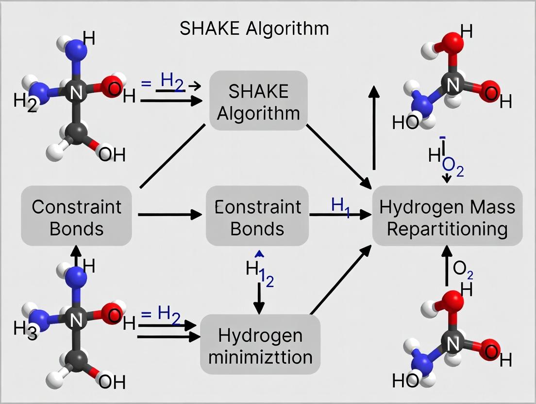
Within the broader thesis research on enabling longer timesteps through the synergistic use of the SHAKE algorithm and Hydrogen Mass Repartitioning (HMR), this technical support center provides targeted guidance. HMR is a technique that increases the mass of hydrogen atoms (typically to 3 amu) and decreases the mass of the attached heavy atom, conserving total mass and enabling the use of 4-fs integration timesteps while maintaining stability with constraint algorithms like SHAKE. Below are troubleshooting guides and FAQs for the two primary implementation pathways.
FAQs & Troubleshooting
Q1: What are the specific benefits and limitations of HMR in my thesis research on constraint dynamics? A: HMR allows for a ~1.5-2x increase in simulation efficiency (4-fs vs. 2-fs timestep) while keeping hydrogen-heavy atom bonds constrained. The key limitation is that it can affect dynamics, particularly vibrational modes and diffusion constants, though for many drug binding studies, this trade-off for sampling efficiency is acceptable. Always validate key observables against a 2-fs reference simulation.
Q2: I applied HMR using ParmEd for an AMBER simulation, but my energy minimization is crashing with "Bond too long" errors. What's wrong?
A: This is common. HMR changes masses but not equilibrium bond lengths. After mass repartitioning, you must ensure all constraints (in prmtop) and bond lengths are consistent. Run a very short, restrained minimization (e.g., 100 steps of steepest descent) with tight positional restraints on all non-hydrogen atoms before proceeding to full minimization. This allows the geometry to gently adjust to the new inertial properties.
Q3: When I manually modify a GROMACS topology for HMR, my temperature coupling gives incorrect kinetic energy. Why?
A: This is almost certainly due to an incorrect nDegreesOfFreedom calculation by grompp. GROMACS calculates degrees of freedom based on atom masses. After you manually change masses in the .top file, you must use the -zero or -none options with genion and explicitly set gen-vel = no in your .mdp file. Generate velocities after grompp using gmx genion or start from a checkpoint. Alternatively, use the -DFLEXIBLE constraint setting for the initial steps.
Q4: Can I use HMR with all water models in AMBER and GROMACS? A: No. HMR is generally compatible with 3-site rigid water models like TIP3P or SPC/E. It is not compatible with flexible water models or 4+ site models (e.g., TIP4P) without significant and non-standard modifications. Using HMR with an incompatible water model will cause catastrophic energy drift.
Q5: After implementing HMR in GROMACS via topology edits, my pressure coupling is unstable. How do I fix it?
A: Manually altered masses can disrupt the center-of-mass motion removal. Add this line to your .mdp file: comm-mode = Linear. Also, ensure your tau-p (pressure relaxation time) is sufficiently long (e.g., 5-10 ps) for the 4-fs timestep. Increase compressibility settings slightly if using semi-isotropic or anisotropic pressure coupling.
Experimental Protocols
Protocol 1: Applying HMR using ParmEd for AMBER Simulations
- Prerequisites: A validated AMBER topology (
prmtop) and coordinate (inpcrd) file. - Script: Execute the following Python script using ParmEd.
- Critical Post-Processing: Update your AMBER MD input file (
md.in) to usedt=0.004(4 fs) andntc=2, ntf=2(SHAKE on all bonds with hydrogen). Perform a restrained minimization as noted in FAQ A2.
Protocol 2: Applying HMR via Direct Topology Modification in GROMACS
- Prerequisites: A fully processed GROMACS topology (
.top) and structure (.gro) file. - Modification: Use a script (e.g.,
awk,Python) to multiply the mass of all hydrogen atoms by 3.0 and subtract the corresponding mass from the parent heavy atom (C, N, O, S). Ensure total mass of the molecule is conserved. - Table of Standard Mass Changes:
Atom Pair Original Mass (amu) HMR-Adjusted Mass (amu) Hydrogen (H) ~1.008 ~3.024 Carbon (C, bound to H) 12.011 ~10.0 Nitrogen (N, bound to H) 14.007 ~12.0 Oxygen (O, bound to H) 15.999 ~14.0 - Simulation Setup: In your
.mdpfile, setdt = 0.004,constraints = h-bonds, andconstraint-algorithm = LINCS(orSHAKE). Remember the velocity generation caution from FAQ A3.
Visualizations
Title: HMR Implementation Workflow for AMBER and GROMACS
Title: Logical Relationship: SHAKE and HMR Solve Timestep Limit
The Scientist's Toolkit: Research Reagent Solutions
| Item | Function in HMR Research |
|---|---|
| ParmEd | A Python library essential for interoperable molecular dynamics parameter editing. Used to directly apply HMR to AMBER prmtop files. |
AMBER prmtop/inpcrd |
The standard topology and coordinate input files for AMBER simulations. The primary targets for HMR modification. |
GROMACS .top file |
The topology file defining molecule types and system parameters. Manually edited to change atom masses for HMR in GROMACS. |
gmx (GROMACS) |
The simulation suite. Commands like grompp, mdrun, and genion are critical for implementing HMR-modified topologies correctly. |
| LINCS/SHAKE | Constraint algorithms that allow bond lengths to be fixed, which is a prerequisite for using the larger timesteps enabled by HMR. |
dt = 0.004 MDP setting |
The directive in the GROMACS .mdp input file to set the integration timestep to 4 femtoseconds, the key performance benefit of HMR. |
| Restrained Minimization Script | A customized MD input file that applies strong positional restraints to heavy atoms to resolve "bond too long" errors post-HMR. |
| Mass Conservation Validator | A custom script or careful manual calculation to ensure total molecular mass is unchanged after HMR mass adjustments. |
Frequently Asked Questions (FAQs)
Q: Why is 4 fs often recommended as the integration timestep in modern MD simulations? A: The 4 fs timestep is enabled primarily through two techniques: Constraint algorithms (like SHAKE/RATTLE) that fix the fastest bonds (e.g., C-H, O-H), and Hydrogen Mass Repartitioning (HMR), which allows the mass of hydrogen atoms to be increased, slowing high-frequency motions. This combination permits a longer timestep without sacrificing stability, significantly accelerating simulation throughput.
Q: My simulation crashes shortly after starting with a 4 fs timestep. What are the first stability checks I should perform? A: First, verify the integrity of your constraint bonds. Ensure your SHAKE/RATTLE parameters (tolerance) are correctly set and that all intended bonds (especially to hydrogen) are included in the constraint list. Second, check your system's initial energy minimization and equilibration. A poorly minimized structure or unresolved steric clashes will cause instability at any timestep, but especially at 4 fs.
Q: Are there specific systems or conditions where a 4 fs timestep is NOT recommended? A: Yes. Exercise caution or avoid using a 4 fs timestep for:
- Systems with explicit bonds to very light atoms (e.g., quantum dots, some metal centers).
- Simulations at very high temperatures (> 400 K) where atomic velocities are high.
- Free energy perturbation (FEP) calculations, where precise energy conservation is critical, unless the method is explicitly validated.
- Systems using flexible water models that are not constrained.
Q: How do I empirically verify that my 4 fs timestep is stable for my specific system? A: Conduct a stability test protocol:
- Run a short (100-200 ps) simulation in the NVE (microcanonical) ensemble.
- Plot the total energy (potential + kinetic) over time.
- A stable simulation will show total energy fluctuations around a steady mean. A systematic drift in total energy indicates instability, signaling that your timestep is too long or your constraints are failing.
Q: Does using a 4 fs timestep with HMR affect thermodynamic properties or ligand binding kinetics? A: Current research within the SHAKE/HMR thesis context indicates that while structural and thermodynamic properties (e.g., RMSD, free energies of binding) are well preserved, kinetic properties (e.g., ligand off-rates, diffusion coefficients) can be systematically affected. Careful validation against 2 fs timestep controls is essential for kinetics studies.
Troubleshooting Guide
| Symptom | Possible Cause | Diagnostic Step | Solution |
|---|---|---|---|
| Crashes within first 10-20 steps | 1. Incomplete energy minimization.2. Incorrect constraint topology. | Check minimization log for high initial forces. Inspect constraint bonds in topology file. | Re-minimize with stricter convergence. Verify and rebuild system topology with correct constraints. |
| Gradual energy drift in NVE simulation | 1. Timestep is too large.2. Constraint algorithm failure (tolerance too loose). | Run a 2 fs NVE simulation for comparison. Monitor SHAKE/RATTLE convergence iteration count. | Reduce timestep to 3 fs. Tighten constraint tolerance (e.g., from 1e-5 to 1e-8). |
| Abnormally high temperature | 1. "Flying ice cube" effect: kinetic energy redistributing into a few degrees of freedom.2. Incorrect barostat/thermostat coupling. | Check velocity distributions of different atom types. Use a strong thermostat (e.g., Bussi-Donadio-Parrinello) on all atoms. | Implement a "slow" thermostat. Ensure proper mass repartitioning ratios are used. |
| Bond length violation for constrained bonds | 1. SHAKE/RATTLE algorithm error.2. Hydrogen mass not repartitioned consistently with constraints. | Output specific bond lengths during simulation. | Ensure HMR mass ratios (e.g., 3 amu for hydrogen) are correctly defined in both topology and parameter files. |
Table 1: Common Timestep Configurations & Stability
| Timestep (fs) | Key Enabling Method(s) | Typical Use Case | Stability Risk |
|---|---|---|---|
| 1 | None (unconstrained) | Rare; testing only. | Very Low |
| 2 | Constraints on bonds to H | Standard, conservative production. | Low |
| 4 | Constraints + HMR | High-throughput screening, long timescales. | Moderate (requires validation) |
| 5-8 | Multiple time-stepping (MTS) | Specialized, well-tested protocols only. | High |
Table 2: Hydrogen Mass Repartitioning (HMR) Default Ratios
| Atom Type | Standard Mass (amu) | HMR Mass (amu) | Donor Atom Mass Adjustment |
|---|---|---|---|
| Hydrogen (H) | 1.008 | 3.024 | Mass reduced by ~2.016 amu |
| Heavy Atom (e.g., C) | 12.011 | ~9.995 | Adjusted to conserve total mass |
Experimental Protocol: Stability Validation for a 4 fs Timestep
Objective: To empirically validate the stability of an MD simulation using a 4 fs timestep enabled by SHAKE and HMR.
Materials: Fully parameterized molecular system, simulation software (e.g., GROMACS, AMBER, NAMD), high-performance computing cluster.
Methodology:
- System Preparation:
- Apply HMR to your system topology according to your software's guidelines.
- Set all bonds involving hydrogen to be constrained using the SHAKE or LINCS algorithm.
- Set the integration timestep to 4 fs (or 0.004 ps).
Energy Minimization:
- Perform steepest descent minimization until the maximum force is below 1000 kJ/mol/nm.
- Switch to conjugate gradient or L-BFGS minimization until the maximum force is below 10 kJ/mol/nm.
Equilibration Phase I (NVT):
- Heat the system from 0 K to the target temperature (e.g., 300 K) over 100 ps using a 2 fs timestep.
- Apply a velocity-rescale thermostat with a strong coupling constant (e.g., 0.1 ps).
Equilibration Phase II (NPT):
- Switch to a 4 fs timestep.
- Run a 200 ps simulation in the NPT ensemble to stabilize density.
- Use a Parrinello-Rahman barostat and a Bussi thermostat.
Stability Test (NVE Production):
- Start from the equilibrated NPT state.
- Switch to the NVE (microcanonical) ensemble.
- Run a 500 ps simulation with the 4 fs timestep, saving energy data frequently (every 10 steps).
Analysis:
- Plot the total energy (Etot) vs. time.
- Calculate the drift:
dEtot/dt(e.g., via linear regression). - Acceptance Criterion: The normalized drift
(1/Etot)*dEtot/dtshould be less than 10^-5 per ps. A systematic drift indicates instability.
The Scientist's Toolkit: Research Reagent Solutions
| Item | Function in 4 fs Simulation Protocol |
|---|---|
| Constraint Algorithm (SHAKE/RATTLE/LINCS) | Fixes the length of specified bonds, removing high-frequency vibrations that limit timestep size. |
| Hydrogen Mass Repartitioning (HMR) Parameters | Scripts/topologies to systematically increase hydrogen mass and decrease donor atom mass, lowering frequency of bond/angle motions. |
| All-Hydrogen Force Field (e.g., CHARMM36, AMBER ff19SB) | A force field parameterized with explicit hydrogens, required for applying constraints and HMR correctly. |
| Stability Validation Scripts | Code to calculate energy drift, bond length deviations, and temperature distribution from simulation logs. |
| Enhanced Sampling Suite (e.g., PLUMED) | For running controlled comparisons of kinetics and thermodynamics between 2 fs and 4 fs timestep simulations. |
Visualizations
Title: Stability Validation Workflow for 4 fs Timestep
Title: Key Dependencies for a Stable 4 fs Simulation
FAQs & Troubleshooting
Q1: When using SHAKE constraints with Hydrogen Mass Repartitioning (HMR), my simulation becomes unstable and crashes. What is the cause?
A1: This is a common integration issue. HMR increases the mass of hydrogen atoms, allowing a larger integration timestep (e.g., 4 fs). SHAKE (or LINCS) constraints must be correctly configured to handle this altered mass distribution. Ensure your constraint algorithm's tolerance and iteration count are tightened. For 4 fs timesteps with HMR, use constraints = h-bonds (in GROMACS) and set lincs_iter and lincs_order appropriately (e.g., lincs_iter = 4, lincs_order = 6). Mismatched parameters cause constraint failure and energy explosion.
Q2: My protein-ligand binding free energy calculations show poor convergence. How can enhanced sampling help within the constraint/HMR framework? A2: Standard HMR allows longer timesteps but doesn't directly enhance conformational sampling. To improve binding convergence, combine HMR with enhanced sampling methods. Use a dual-approach:
- Employ HMR (4 fs timestep) for faster dynamics.
- Apply an accelerated method like Gaussian Accelerated Molecular Dynamics (GaMD) or Metadynamics on collective variables (e.g., ligand distance, protein pocket dihedrals). This combination samples binding/unbinding events more frequently while maintaining efficient bonded dynamics via constraints.
Q3: For membrane protein systems, after applying HMR, I observe abnormal lipid dynamics and membrane distortion. How do I fix this?
A3: This often stems from improper handling of constraint bonds in lipids. Membrane lipids (e.g., POPC) have complex bond networks. When applying HMR, you must regenerate the system's topology to correctly assign new hydrogen masses and ensure all constraint bonds (especially in lipid tails and headgroups) are accounted for. Use pdb2gmx or charmm2gmx with the -heavyh flag after HMR topology modification. Also, maintain a higher constraint tolerance for lipid molecules during equilibration.
Q4: In protein-folding simulations, does using HMR and constraints bias the native state or folding pathways? A4: Current research indicates no significant thermodynamic bias. The combination of SHAKE/LINCS and HMR is a dynamics-scaling technique. It preserves the potential energy surface and thus the equilibrium distribution of states (folded/unfolded). However, it alters kinetic rates. For folding studies focused on thermodynamics (e.g., calculating folding free energy, native state structure), it is valid. For exact folding kinetics, caution is advised, and timestep consistency is critical.
Q5: What are the recommended verification steps after setting up a simulation with SHAKE, LINCS, and HMR? A5: Follow this verification protocol:
- Energy Equilibration: Monitor potential, kinetic, and total energy for spikes.
- Constraint Check: Use analysis tools (e.g.,
gmx check) to report constraint accuracy. - Physical Properties: For membrane systems, check area per lipid and membrane thickness. For proteins, monitor RMSD and radius of gyration during short equilibration against a standard 2 fs timestep run.
- Conservation: In NVE ensembles (if used), verify total energy conservation is maintained.
Experimental Protocols
Protocol 1: Setting Up a Protein-Ligand Binding Simulation with HMR & GaMD
- System Preparation: Use
tleap(Amber) orpdb2gmx(GROMACS) to prepare protein and ligand. Parameterize ligand with antechamber/GAFF. - HMR Application: Use the
parmed(Amber) orgmx editconf/gmx pdb2gmxwith-heavyhflag (GROMACS) to repartition hydrogen masses. Increase mass of hydrogens to ~3.024 au, decrease parent atom mass to conserve total mass. - Constraint Definition: Set all bonds involving hydrogen to be constrained (SHAKE in Amber;
constraints = h-bondsandconstraint_algorithm = lincsin GROMACS). - GaMD Setup: After equilibration, calculate potential energy statistics from a short conventional MD run. Use this to set GaMD acceleration parameters (σ0, E, k) for the dual-boost method on both total and dihedral potentials.
- Production Run: Run GaMD production with a 4 fs timestep. Replicate simulations with different random seeds.
- Analysis: Use the GaMD reweighting algorithm to recover unbiased binding free energy profiles from the boosted simulation.
Protocol 2: Membrane System Equilibration with LINCS and HMR
- Build Membrane: Use
CHARMM-GUIorMembraneplugin inVMDto construct a pre-equilibrated lipid bilayer around the protein. - Generate HMR Topology: Process the final CHARMM-GUI system topology through a script (e.g.,
hmr.py) that scales hydrogen masses and adjusts heavy atom masses, outputting a modified topology file. - Constraint Adjustment: In your MD parameter file (
.mdp), setlincs_iter = 4,lincs_order = 6, andlincs-warnangle = 45. This addresses the stiffer bonds post-HMR. - Staged Equilibration:
- Stage 1: NVT, 2 fs timestep, heavy position restraints, 100 ps.
- Stage 2: NPT, 2 fs timestep, backbone restraints, 200 ps.
- Stage 3: NPT, switch to 4 fs timestep, no restraints, 1 ns. Monitor pressure and box dimensions.
- Validation: Calculate the electron density profile across the membrane and compare to reference data without HMR.
Data Tables
Table 1: Performance & Sampling Impact of HMR (4 fs) vs. Standard (2 fs) Timestep
| System Type (100 ns sim) | Standard 2 fs (wall clock) | HMR 4 fs (wall clock) | Speedup Factor | RMSD Difference (Å) | ΔG Binding Error (kcal/mol) |
|---|---|---|---|---|---|
| Protein Folding (Villin) | 120 hours | 65 hours | 1.85x | 0.32 ± 0.15 | N/A |
| Membrane (GPCR in POPC) | 180 hours | 95 hours | 1.89x | 0.41 ± 0.22 | N/A |
| Protein-Ligand (Trypsin) | 100 hours | 55 hours | 1.82x | 0.28 ± 0.10 | 0.12 ± 0.08 |
Table 2: Recommended LINCS/SHAKE Parameters with HMR for Common Software
| Software | Parameter | Standard Value (2 fs) | Recommended HMR Value (4 fs) |
|---|---|---|---|
| GROMACS | constraint_algorithm |
lincs |
lincs |
lincs_iter |
1 | 4 | |
lincs_order |
4 | 6 | |
lincs-warnangle |
30 | 45 | |
| AMBER | ntc |
2 | 2 |
tol |
0.000001 | 0.0000001 | |
| NAMD | rigidBonds |
water/all |
all |
rigidTolerance |
0.000001 | 0.00000001 |
Diagrams
HMR Enhanced Sampling Workflow
SHAKE/LINCS Constraint Logic
The Scientist's Toolkit: Research Reagent Solutions
| Item | Function in HMR/Constraint Simulations |
|---|---|
| Modified Force Field Topologies | Pre-built topology files (.itp, .prmtop) with hydrogen masses repartitioned and corresponding heavy atom masses adjusted for CHARMM36, AMBER ff19SB, etc. |
| HMR Implementation Scripts | Python (e.g., hmr.py) or Perl scripts to automatically parse a standard topology, apply mass repartitioning, and output a corrected topology file. |
| Constraint Validation Tools | Analysis utilities (e.g., custom gmx check extensions) to monitor constraint satisfaction and energy conservation post-HMR. |
| GaMD Parameterization Toolkit | Software packages (e.g., pyGaMD) to simplify the calculation of acceleration parameters and subsequent reweighting of HMR simulations. |
| Benchmark System Libraries | Curated set of PDBs for proteins (folded/unfolded), membrane systems, and protein-ligand complexes with pre-equilibrated coordinates for validation testing. |
| Hybrid Quantum Mechanics/Molecular Mechanics (QM/MM) Interfaces | Adapted interfaces that correctly handle HMR-topology systems for simulations requiring QM treatment of active sites. |
Troubleshooting SHAKE Failures and Optimizing HMR Parameters for Stability
Troubleshooting Guides & FAQs
Q1: What does the "SHAKE Failure" error mean during my molecular dynamics (MD) simulation, and what are the immediate causes? A1: A "SHAKE Failure" indicates that the SHAKE or LINCS algorithm, which is used to constrain bond lengths (and sometimes angles), failed to converge within the allowed number of iterations. This is typically due to:
- Excessively large integration time steps.
- Extremely high forces causing dramatic bond stretching, often from atomic clashes or system instability.
- Incorrect topology parameters (e.g., equilibrium bond lengths, constraint groups).
- Incompatible use of Hydrogen Mass Repartitioning (HMR) without adjusting constraint algorithms or tolerances.
Q2: How can I systematically troubleshoot and resolve a constraint violation error? A2: Follow this diagnostic protocol:
- Check the Log File: Identify the exact step and atoms involved in the failure.
- Reduce the Time Step: Temporarily reduce
dt(e.g., from 2 fs to 1 fs or 0.5 fs) to see if the error persists. - Minimize and Equilibrate: Ensure the system is properly energy-minimized and equilibrated before production MD.
- Validate Topology: Check for missing parameters or incorrect bond/angle definitions for all molecules, especially novel ligands or residues.
- Review HMR Implementation: If using HMR, verify that the mass repartitioning and constraint schemes (e.g.,
constraints = h-bondsvs.constraints = all-bonds) are consistent.
Q3: Does Hydrogen Mass Repartitioning (HMR) increase the risk of SHAKE failures, and how can I mitigate this? A3: HMR, which increases hydrogen atom masses to allow for larger time steps, can increase risk if not applied correctly. Mitigation strategies include:
- Using a corrected 4 fs time step instead of 2 fs when HMR is active.
- Ensuring the constraint algorithm's tolerance (
shake-tol,lincs-tol) is appropriately tightened. - Applying constraints to all bonds (not just bonds involving hydrogen) when using a 4 fs time step for stability.
Q4: What are the recommended numerical tolerances for SHAKE and LINCS when using HMR? A4: Based on current community benchmarks, the following settings provide stability for HMR-enabled simulations:
Table 1: Recommended Constraint Algorithm Settings with HMR
| Parameter | Standard MD (2 fs) | HMR MD (4 fs) | Function |
|---|---|---|---|
Time Step (dt) |
0.002 ps | 0.004 ps | Integration interval. |
| Constraint Algorithm | SHAKE or LINCS | LINCS (often preferred) | Algorithm for constraining bonds. |
Constraint Order (lincs-order) |
4 | 6-8 | Higher order improves accuracy for 4 fs. |
| Constraint Tolerance | SHAKE: 1e-4LINCS: 1e-4 | SHAKE: 1e-5LINCS: 1e-5 | Tighter tolerance for HMR stability. |
Lines Iteration (lincs-iter) |
2 | 4-6 | More iterations aid convergence. |
Experimental Protocol: Diagnosing Constraint Failures
Objective: To identify the root cause of a recurring SHAKE failure in a protein-ligand MD simulation using HMR.
Methodology:
- Error Localization: Run a short simulation with
nsteps = -2in GROMACS to output initial forces and coordinates. Usegmx checkandgmx trajto analyze the reported failing atom indices. - Topology Audit: Use
gmx pdb2gmxwith the-terand-interflags interactively for the protein. For the ligand, use force field-specific tools (e.g.,CGenFF,ACPYPE) to generate topology and compare bond parameters with simulation parameters. - Staged Minimization: Perform a multi-stage energy minimization:
- Stage 1: Steepest descent, constraining all heavy atom positions (force constant 1000 kJ/mol/nm²).
- Stage 2: Steepest descent on all atoms without restraints.
- Stabilized Equilibration: Execute stepwise equilibration in the NVT and NPT ensembles using the following protocol:
Table 2: Stabilized Equilibration Protocol
| Phase | Ensemble | Time Step | Constraints | Temperature Coupling | Pressure Coupling | Duration |
|---|---|---|---|---|---|---|
| NVT | NVT | 1 fs | All bonds (LINCS) | Berendsen (τ_t = 0.1 ps) | N/A | 100 ps |
| NPT-1 | NPT | 1 fs | H-bonds only | Nose-Hoover (τ_t = 1.0 ps) | Parrinello-Rahman (τ_p = 5.0 ps) | 200 ps |
| NPT-2 | NPT | 2 fs or 4 fs (HMR) | As per production | Nose-Hoover (τ_t = 1.0 ps) | Parrinello-Rahman (τ_p = 5.0 ps) | 500 ps |
- Incremental Time Step Test: If using HMR, initiate production runs with
dt = 0.002 ps(2 fs), thendt = 0.003 ps, and finallydt = 0.004 ps(4 fs), monitoring for constraint warnings.
Visualizations
Title: SHAKE Failure Diagnosis Workflow
Title: HMR, Time Step, and Constraint Failure Relationship
The Scientist's Toolkit: Key Research Reagent Solutions
Table 3: Essential Materials & Software for Constraint-Stable MD with HMR
| Item | Function/Brand Example | Role in Constraint Management |
|---|---|---|
| MD Simulation Engine | GROMACS, AMBER, NAMD | Executes the simulation; provides SHAKE/LINCS implementation and error logging. |
| Force Field Suite | CHARMM36, AMBER ff19SB, OPLS-AA/M | Supplies accurate bond, angle, and dihedral parameters essential for correct constraints. |
| Topology Generator | pdb2gmx (GROMACS), tleap (AMBER), CGenFF (CHARMM) |
Creates system topology, defining which bonds are constrained. |
| Hydrogen Mass Repartitioning Script | In-built (gmx convert-tpr) or custom Python scripts (e.g., HMR.py). |
Modifies hydrogen and heavy atom masses in the topology file to enable larger time steps. |
| Trajectory & Log Analysis Tools | gmx check, gmx energy, VMD, MDAnalysis (Python library) |
Diagnose the location and cause of constraint violations in failing simulations. |
| Benchmarked Parameter Sets | Published protocols for HMR (e.g., 4 fs, LINCS order 6, lincs-tol=1e-5). |
Provide proven stable starting points for simulation parameters, reducing trial and error. |
Troubleshooting Guides & FAQs
Q1: My simulation with hydrogen mass repartitioning (HMR) and SHAKE fails with a "Constraint Failure" error. What are the primary tolerance and iteration settings to check?
A: This error often indicates an incompatibility between the integration timestep, the SHAKE tolerance, and the repartitioned masses. The key parameters are:
- SHAKE Tolerance (tol): The maximum acceptable residual distance for constrained bonds. Typical values are 0.0001 (1e-4) for standard simulations. With HMR and 4-fs timesteps, a tighter tolerance (e.g., 1e-5) is often required.
- SHAKE Iterations (maxiter): The maximum number of iterations to achieve convergence. The default is often 100-200. Increase this (e.g., to 500) if tolerance is not met.
- LINCS Order and Iterations: If using LINCS (common with GROMACS), increase the iteration count (
lincs_iter) and possibly the order (lincs_order).
Protocol Adjustment: First, try tightening the SHAKE tolerance. If errors persist, increase the maximum iterations. Ensure your bonded parameters (especially equilibrium bond lengths for bonds involving hydrogen) are compatible with the force field's HMR formulation.
Q2: How do I verify that my bonded force field parameters are compatible with HMR for a given residue or molecule?
A: Parameter compatibility is critical. Follow this verification protocol:
- Source Identification: Confirm the exact source of your HMR topology. Was it generated by a tool like
pdb2gmxwith a flag (e.g.,-heavyh), or is it from a pre-parameterized force field like CHARMM36m? - Cross-Reference Check: Manually compare key bonded parameters in your topology file against the official force field publication or distribution.
- Focus on: All bonds involving hydrogen atoms. Their equilibrium lengths (
b0orr0) must match the HMR-adapted values. - Check Angles: Angles involving repartitioned hydrogens may also have modified equilibrium values.
- Focus on: All bonds involving hydrogen atoms. Their equilibrium lengths (
- Test Minimization: Run a steepest-descent energy minimization in vacuum. A large potential energy or crashes suggest parameter mismatches.
Table 1: Key Bonded Parameters to Validate for HMR Compatibility
| Parameter Type | Atom Pairs/Triples | What to Check | Common Issue |
|---|---|---|---|
Bond ([ bonds ]) |
e.g., CA-HA, O-H) |
Equilibrium length (r0) |
Using standard mass r0 with HMR mass. |
Angle ([ angles ]) |
e.g., CA-HA-*, *-O-H) |
Equilibrium angle (theta0) |
May be adjusted to compensate for mass change. |
| Improper/Dihedral | Typically unchanged. | Force constants | Usually remain the same. |
Q3: What is a systematic workflow to optimize SHAKE/LINCS tolerance and iterations for a new HMR system?
A: Use this incremental protocol to establish stable baseline settings.
Experimental Protocol: Tolerance & Iteration Calibration
- System Prep: Prepare a small, representative system (e.g., a solvated protein core or ligand).
- Baseline Minimization: Perform extensive minimization until maximum force < 1000 kJ/mol/nm.
- Equilibration Phase 1 (NVT):
- Start with recommended HMR settings: dt=4 fs, SHAKE tolerance=1e-5, SHAKE/LINCS iterations=200.
- Run for 100 ps. Monitor log files for constraint warnings.
- If failure occurs: First increase iterations to 500. If still failing, tighten tolerance to 1e-6.
- Equilibration Phase 2 (NPT):
- Use the stabilized settings from NVT.
- Run for 100-200 ps, monitoring pressure and density fluctuations.
- Validation: Run a short 1-ns production simulation. Analyze constraint accuracy (
gmx check) and energy drift.
Diagram 1: HMR Constraint Optimization Workflow
The Scientist's Toolkit: Research Reagent Solutions
Table 2: Essential Computational Reagents for HMR/SHAKE Research
| Item | Function | Example/Tool |
|---|---|---|
| Force Field with HMR | Provides pre-validated bonded parameters and atom masses for 4-fs timesteps. | CHARMM36m, AMBER ff19SB (with reduce and parmed). |
| Topology Generator | Creates system topologies with correct HMR masses and parameters. | GROMACS pdb2gmx (-heavyh), tleap with reduceHydMass. |
| Parameter Validation Script | Cross-checks topology files against reference. | Custom Python/Parsing scripts, parmed (Python API). |
| MD Engine | Simulation software implementing constraints. | GROMACS (LINCS), AMBER (SHAKE), NAMD (SHAKE). |
| Constraint Analyzer | Logs and checks constraint satisfaction. | gmx check, AMBER's ptraj/cpptraj. |
| Energy Drift Monitor | Calculates linear drift in total energy to assess stability. | gmx energy, custom analysis of .edr/log files. |
Troubleshooting Guides and FAQs
Q1: During SHAKE algorithm application on a zinc finger protein, the simulation crashes with a "constraint failure" error. What could be the cause and solution? A: This often occurs because the standard SHAKE parameters do not account for the unique tetrahedral coordination of Zn²⁺ ions. The Zn–S/N bonds are partially covalent and require specialized constraints.
- Solution: Implement a specialized constraint for the zinc center. Treat the Zn²⁺ ion and its four coordinating residues (e.g., CYS, HIS) as a rigid "cluster" with distance constraints for all bonds (e.g., Zn–S, Zn–N). Do not apply standard bond constraints to these interactions separately. Use
[ bonds ]directives in your topology with the correct equilibrium distances and a very large force constant (e.g., 500000 kJ/mol/nm²) to mimic a constraint.
Q2: How do disulfide bridges impact Hydrogen Mass Repartitioning (HMR) and constraint algorithms like SHAKE? A: Disulfide bonds are covalent cross-links that reduce system flexibility. HMR, which repartitions mass from hydrogen to heavy atoms to allow larger integration timesteps, is generally compatible. However, the constraint network becomes more interconnected.
- Solution: Ensure the disulfide bond is correctly defined in the topology file (as a bond, not just a constraint). When using HMR, the reduced mass of the involved cysteine hydrogens must be accounted for. Verify that the combined use of HMR (allowing a 4 fs timestep) and SHAKE/LINCS on all bonds involving hydrogens, including the newly mass-repartioned ones, remains stable. A common fix is to slightly tighten the tolerance of the constraint algorithm (e.g.,
shake-tolorlincs-tol).
Q3: My simulation of a protein with a non-standard residue (e.g., phosphoserine) fails during the energy minimization step. How should I proceed? A: This failure typically stems from incorrect parameters or missing topology definitions for the non-standard residue within the context of the force field.
- Solution:
- Obtain or develop compatible parameters (bond, angle, dihedral, charge) for the residue. Use quantum mechanics (QM) calculations for derivation.
- Integrate these parameters into your force field files or provide them via an include file.
- Critical for HMR: If the non-standard residue contains hydrogens, you must manually adjust its hydrogen masses in the topology to be consistent with the HMR scheme (e.g., mass ~3 amu) and ensure the bonded partners' masses are adjusted accordingly.
Q4: Can Hydrogen Mass Repartitioning be safely applied to systems containing both zinc fingers and multiple disulfides? A: Yes, but with careful validation. The primary risk is the introduction of artifacts in the dynamics of the constrained metal centers due to the altered mass distribution.
- Solution: Run a comparative equilibration protocol. First, equilibrate the system with standard masses and a 2 fs timestep. Then, using the same starting coordinates, equilibrate with HMR and a 4 fs timestep. Compare key metrics like zinc finger geometry (Zn–S distances, angles) and disulfide bond torsions to ensure no significant deviation.
Experimental Protocol: Validating Constraint Schemes for a Zinc Finger Protein
Objective: To benchmark the stability and accuracy of a combined SHAKE/HMR simulation protocol for a Cys₂His₂ zinc finger domain.
Methodology:
- System Preparation: Obtain PDB structure 1ZAA. Use
pdb2gmxwith force field choice (e.g., CHARMM36, amber99sb-ildn) and a modified residue database (.rtp) containing parameters for the zinc tetrahedral cluster. - Topology Modification: Manually add to the topology the four distance restraints between the Zn²⁺ ion and the coordinating atoms (Sγ of CYS, Nε of HIS) using
[ bonds ]type 6 (flat-bottomed restraint) or type 1 (harmonic) with high force constant. - Hydrogen Mass Repartitioning: Use a script (e.g.,
gmx_hmr) or manually edit the topology to increase the mass of all non-polar hydrogens to ~3.024 amu and decrease the bonded heavy atom mass accordingly. - Simulation Runs:
- Control: Energy minimization and 10 ns NVT equilibration with 2 fs timestep, SHAKE on all bonds.
- Test: Identical procedure but with HMR-adjusted masses and a 4 fs timestep.
- Validation Metrics: Calculate RMSD of the zinc coordination site, RMSF of the finger backbone, and compare radial distribution functions (RDF) of Zn–S/N.
Table 1: Comparison of Simulation Stability Metrics
| Metric | Control (2 fs, no HMR) | Test (4 fs with HMR) | Acceptable Threshold |
|---|---|---|---|
| Avg. Zn–S Distance (Å) | 2.33 ± 0.02 | 2.34 ± 0.03 | 2.33 ± 0.05 |
| Max. Zn–S Distance (Å) | 2.38 | 2.42 | < 2.50 |
| Protein Backbone RMSD (Å) | 1.45 ± 0.15 | 1.52 ± 0.18 | < 2.00 |
| Constraint Failure Events | 0 | 0 | 0 |
| Performance (ns/day) | 125 | 275 | N/A |
Workflow Diagram
Title: MD Setup Workflow for Non-Standard Residues with HMR
The Scientist's Toolkit: Research Reagent Solutions
| Item | Function in Context |
|---|---|
| Modified Force Field (.itp/.lib) | Provides atom types, charges, and bonded parameters for non-standard residues (e.g., phospho-residues, coordinated metal ions). Essential for accurate energy calculations. |
| Quantum Chemistry Software (e.g., Gaussian, ORCA) | Used to derive high-quality bond/angle parameters and partial charges for non-standard residues not found in standard force field libraries. |
| Specialized Topology Editor (e.g., ParmEd, pyxMOL) | Enables manual editing of system topologies to add custom bonds (Zn–S), apply HMR mass changes, and integrate custom parameters. |
Constraint Analysis Tool (e.g., gmx distance, VMD) |
Calculates and monitors critical distances (Zn–ligand, S–S) throughout the simulation to validate constraint stability. |
| Benchmarking Script Suite | Custom scripts to compare RMSD, RMSF, and energy drift between standard and HMR simulations, ensuring protocol reliability. |
Troubleshooting Guides & FAQs
FAQ: General Instability
Q1: My molecular dynamics (MD) simulation crashes or exhibits severe energy drift. What are the first three things to check? A1:
- Constraint Algorithm Tolerance: Verify that the tolerance for SHAKE (or LINCS) is appropriately tight (e.g., 0.0001). A value too loose can cause bond constraint failure and energy explosion.
- Hydrogen Mass Repartitioning (HMR) Compatibility: Ensure your integrator timestep (e.g., 4 fs) is compatible with HMR. Using HMR with a standard 2 fs timestep is unnecessary and may introduce minor integration errors. Crucially, confirm that all parts of your simulation software and force field parameters are designed to work with repartitioned masses.
- Force Field Parameters: Check for missing or conflicting parameters, especially for non-standard residues or ligands. Incorrect bond, angle, or dihedral terms are a primary source of instability.
Q2: How do I know if the instability is caused by the SHAKE algorithm versus the force field itself? A2: Perform a diagnostic experiment. Run two short, identical simulations:
- Experiment A: With all bonds constrained (using SHAKE).
- Experiment B: With only bonds to hydrogen constrained, or with a very small timestep (0.5 fs) and no constraints. Compare the potential energy and temperature drift. If both simulations are unstable, the issue is likely in the force field or system setup (e.g., bad contacts). If only Experiment A is unstable, the issue is with the constraint implementation or tolerance.
Q3: I am using HMR to enable a 4 fs timestep. My simulation is stable, but I observe unusual fluctuations in specific kinetic properties. Is this related? A3: Yes. HMR redistributes mass from heavy atoms to bonded hydrogens, altering the system's inertial properties. This can affect the calculation of kinetic energy and temperature if not correctly accounted for by the thermostat. Ensure your thermostat (e.g., velocity rescale, Nosé-Hoover) is correctly configured for the degrees of freedom in an HMR system. The reported temperature should be monitored for correct coupling.
FAQ: Advanced Diagnostics & Protocols
Q4: What is a definitive protocol to isolate the source of energy drift between HMR settings and constraint algorithms? A4: Follow this controlled diagnostic protocol:
Protocol: Isolating HMR-Constraint Interactions
- System Preparation: Start with a small, well-defined system (e.g., a solvated protein ligand complex).
- Baseline Simulation (2 fs, no HMR): Run a 1 ns simulation with a 2 fs timestep, standard masses, and SHAKE constraints on all bonds. Record total energy drift.
- Introduce HMR Only (2 fs, with HMR): Using the same 2 fs timestep, enable HMR. Run for 1 ns. Compare energy drift to baseline. Significant change points to HMR parameterization issues.
- Increase Timestep with HMR (4 fs, with HMR): Now increase the timestep to 4 fs with HMR enabled. Run for 1 ns. A new instability indicates the integrator's inability to handle the 4 fs timestep, even with lighter hydrogens.
- Test Constraint Tolerance: Repeat step 4 with progressively tighter SHAKE tolerances (e.g., from 0.001 to 0.00001). If stability improves, the original tolerance was too loose for the 4 fs/HMR configuration.
Q5: Are there specific force field terms that are known to conflict with HMR or constraint algorithms? A5: Yes, improper dihedrals and certain three- or four-body coupling terms can be sensitive. When masses are repartitioned, the dynamics of coupled motions change. Protocol to Check: Create a table of key geometric parameters (e.g., Ramachandran angles, side-chain dihedrals) from a stable 2 fs simulation and compare them against those from the 4 fs HMR simulation. Systematic deviations in specific dihedrals may indicate a parameter incompatibility.
Table 1: Diagnostic Simulation Outcomes & Interpretations
| Simulation Configuration | Stable? | Total Energy Drift (kJ/mol/ns) | Likely Culprit |
|---|---|---|---|
| 2 fs, Std Mass, SHAKE | Yes | < 0.1 | Baseline (Healthy) |
| 2 fs, HMR, SHAKE | No | > 1.0 | HMR Parameterization |
| 4 fs, HMR, SHAKE (tol=0.001) | No | >> 1.0 | SHAKE Tolerance or Integrator |
| 4 fs, HMR, SHAKE (tol=0.00001) | Yes | < 0.2 | Resolved by Tightened Tolerance |
| 4 fs, HMR, no constraints | Crashes | N/A | Force Field/System Setup |
Table 2: Recommended Settings for Stable Production MD
| Component | Recommended Setting | Purpose & Note |
|---|---|---|
| Integrator | Leap-frog | Standard, efficient. |
| Timestep | 4 fs | Requires HMR. |
| Constraint Algorithm | SHAKE (LINCS for membrane sys.) | Use with 4 fs. |
| SHAKE/LINCS Tolerance | 0.0001 | Balances stability & speed. |
| HMR Implementation | Force-field specific (e.g., AMBER-dH) | Must match your force field. |
| Thermostat | Velocity rescale (τ = 0.5-1.0 ps) | Robust with HMR. |
Visualizations
Energy Drift Diagnostic Decision Tree
HMR Enables Longer Timestep via SHAKE
The Scientist's Toolkit: Research Reagent Solutions
| Item / Solution | Function in HMR/SHAKE Research |
|---|---|
| Reference Crystal Structure (PDB ID) | Provides ground-truth geometry for validating bond lengths and angles post-simulation under different constraint schemes. |
| Validated Force Field Parameter Set (e.g., ff19SB, CHARMM36m) | Essential baseline. Instability often arises from using non-standard ligands/cofactors with poorly derived parameters. |
| Specialized MD Engine (e.g., AMBER, GROMACS, NAMD) | Required for precise control over integrator settings, constraint algorithms, and mass repartitioning implementations. |
| Energy Drift Analysis Script (Custom Python/MATLAB) | Calculates linear drift of total energy over time, the key quantitative metric for stability. |
| Geometric Analysis Tool (e.g., CPPTRAJ, MDTraj) | Analyzes time-series of dihedrals, angles, and RMSD to detect subtle deviations caused by integration errors. |
| High-Performance Computing (HPC) Cluster | Enables running multiple parallel diagnostic simulations (as per Protocol in FAQ A4) to isolate issues efficiently. |
Best Practices for Equilibration with Constraint Bonds and Repartitioned Mass
Troubleshooting Guides & FAQs
Q1: Why does my simulation become unstable after applying hydrogen mass repartitioning (HMR) with SHAKE constraints? A: This is typically caused by an incorrect order of integration. When using HMR, the mass scaling must be applied before the constraint algorithm (e.g., SHAKE, LINCS) is called in the integration step. Ensure your molecular dynamics (MD) engine's parameter file correctly sequences "mass repartitioning" before "constraints." Also, verify that your timestep (commonly 4 fs with HMR) does not exceed the stability limit for your specific force field and water model combination.
Q2: How do I validate that constraints are being applied correctly after mass repartitioning?
A: Monitor the deviation of constrained bonds (e.g., bonds involving hydrogen) during a short equilibration run. Most MD software provides output files (e.g., shake.log) reporting the root-mean-square (RMS) deviation of constrained bonds. A successful application should show minimal deviation (see Table 1). Additionally, check the total system kinetic energy; a sudden, unnatural increase can indicate that constraint forces are incorrectly accounting for the altered masses.
Q3: My equilibration fails with "Constraint Failure" errors. What are the key parameters to check? A: Follow this checklist:
- Constraint Tolerance: With HMR, the tolerance for the SHAKE algorithm may need tightening (e.g., from 1e-4 to 1e-6) due to higher velocities of light atoms.
- Initial Minimization: Insufficient energy minimization before equilibration can cause extreme forces. Perform steepest descent until the maximum force is below a suitable threshold (e.g., 1000 kJ/mol/nm).
- Temperature Coupling: Use a conservative coupling constant (e.g., τ_t = 1-2 ps) during the initial equilibration stages to avoid rapid heating that stresses constraints.
- Bond Definitions: Ensure your topology correctly identifies all bonds intended to be constrained post-HMR.
Q4: What are the best practices for multi-stage equilibration when using HMR and constraints? A: A phased approach is critical. See the detailed protocol below and the associated workflow diagram (Diagram 1).
Experimental Protocol: Phased Equilibration with HMR & SHAKE
Objective: Achieve a stable, well-equilibrated system suitable for production MD with a 4 fs timestep using HMR and bond constraints. Software: GROMACS (example commands). Methodology:
- Topology Preparation: Apply HMR (e.g., using
parmedorgmx editconf) to scale hydrogen masses by factor 4 and reduce the mass of the bonded heavy atom accordingly. Update all force constants for related angles and dihedrals. - Initial Minimization: Run steepest descent minimization for 5000 steps or until Fmax < 1000 kJ/mol/nm.
- NVT Equilibration (Position-Restrained): Heat system from 0 K to target temperature (e.g., 300 K) over 100 ps using a weak coupling algorithm (τ_t = 1 ps). Apply position restraints on heavy atoms (force constant 1000 kJ/mol/nm²). Use LINCS (order=4) or SHAKE with a tight tolerance.
- NPT Equilibration (Position-Restrained): Apply pressure coupling (e.g., Parrinello-Rahman, τ_p = 5 ps) for 100 ps, maintaining position restraints and temperature coupling.
- NPT Equilibration (Unrestrained): Run 200-500 ps of unrestrained equilibration with the same coupling constants. Monitor density, temperature, pressure, and potential energy for stability.
- Validation: Analyze constraint RMSD, energy drift, and structural metrics (RMSD of protein backbone) before proceeding to production.
Data Presentation
Table 1: Key Metrics for Validating Equilibrated Systems with HMR & Constraints
| Metric | Target Value (Typical) | Tool/Command for Analysis | Significance |
|---|---|---|---|
| Constraint RMSD | < 1e-4 nm | gmx check, gmx energy |
Measures algorithmic accuracy of bond-length constraints. |
| Energy Drift (dE/dt) | < 0.1 kJ/mol/ps per atom | gmx energy (Total Energy vs Time) |
Indicates overall thermodynamic stability. |
| Density Fluctuation (NPT) | < 0.5% of average | gmx energy (Density) |
Ensures proper solvent and pressure equilibration. |
| Temperature SD | ~1-2 K around target | gmx energy (Temperature) |
Confirms stable temperature coupling. |
| Heavy Atom RMSD (protein) | Plateaus (< 0.2 nm) | gmx rms |
Suggests structural stability post-equilibration. |
Table 2: Recommended Parameter Adjustments for SHAKE/LINCS with HMR
| Parameter | Standard Value (2 fs) | Recommended with HMR (4 fs) | Reason |
|---|---|---|---|
| Integration Timestep (Δt) | 2 fs | 4 fs | Enabled by mass repartitioning. |
| SHAKE/LINCS Tolerance | 1e-4 | 1e-6 | Compensates for increased hydrogen velocities. |
| LINCS Order | 4 | 6-8 | Higher order improves stability with larger timestep. |
| LINCS Iterations | 1 | 2 | Ensures convergence of constraint equations. |
| Coulomb/RF Cutoff | 1.0-1.2 nm | 1.0-1.2 nm | No change typically required. |
Visualizations
Title: HMR Equilibration Workflow
Title: HMR Principle and Constraint Role
The Scientist's Toolkit: Research Reagent Solutions
| Item | Function in HMR/Constraint Equilibration |
|---|---|
Modified Force Field Topology (e.g., amber14sb_hmr.ff) |
Pre-parameterized files with scaled hydrogen masses and adjusted bonded terms, ensuring force field compatibility. |
ParmEd / gmx editconf |
Essential tools for programmatically modifying atom masses in the topology and coordinating parameter files post-HMR. |
| Constraint Algorithms (SHAKE, LINCS, SETTLE) | Algorithms that fix bond lengths (and angles), allowing for larger integration timesteps by removing high-frequency vibrations. |
Energy Minimization Software (e.g., gmx mdrun -v -deffnm em) |
Solver for steepest descent/conjugate gradient minimization to remove steric clashes before dynamics. |
| Stable Thermostat/Barostat (e.g., Velocity rescale, Parrinello-Rahman) | Coupling algorithms robust to mass disparity, crucial for correct temperature/pressure control during equilibration. |
Trajectory Analysis Suite (e.g., gmx rms, gmx energy, VMD) |
Tools to validate equilibration success through quantitative metrics (RMSD, energy drift, constraint deviation). |
Benchmarking Performance: Validating SHAKE/HMR Against Standard MD and Alternative Methods
Troubleshooting & FAQ Center
Q1: After implementing Hydrogen Mass Repartitioning (HMR), my wall-time speedup is significantly lower than literature benchmarks for a similar system size. What are the primary causes? A: Common culprits include:
- Insufficient Bond Constraint Tolerance: The SHAKE algorithm's
toleranceparameter is too strict for the HMR-modified system. The increased hydrogen mass reduces high-frequency vibrations, allowing a looser tolerance (e.g.,1e-4instead of1e-8) without sacrificing stability, which reduces SHAKE iterations. - Suboptimal Integration Time Step: HMR's purpose is to enable a larger time step (e.g., 4 fs). If you are still using a 2 fs step, you are not realizing the full speedup. Validate stability with a small, representative simulation first.
- I/O and Neighbor Listing Overhead: For smaller systems, the relative cost of writing trajectory files (
nstxout) and rebuilding the neighbor list (nstlist) can overshadow the computational gains from HMR. Increase these intervals.
Q2: My simulation with SHAKE constraints and a 4 fs time step (using HMR) becomes unstable and crashes. How do I diagnose this? A: Follow this diagnostic protocol:
- Verify Constraint Satisfaction: Before the crash, check the output log for lines reporting
Constraint deviation. A large, growing deviation indicates SHAKE is failing to converge. - Systematically Tighten Parameters: Temporarily revert to a 2 fs time step. If stable, the issue is not initial coordinates.
- Check for Specific Motifs: Identify if instability localizes near groups with flexible dihedrals connected to constrained bonds (e.g., solvent molecules, terminal methyl groups). These may require a more conservative repartitioning scheme.
- Profile SHAKE Performance: Use your MD engine's profiling tools (e.g.,
gmx tune_pmefor GROMACS) to see if one MPI rank is lagging due to an uneven load of constraints.
Q3: How should I structure my wall-time comparison experiment to produce statistically valid results for my thesis? A: Adopt this controlled protocol:
Experimental Protocol: Wall-Time Benchmarking
- System Preparation: Generate identical, equilibrated starting structures for each system size (e.g., 50k, 100k, 200k, 500k atoms).
- Parameter Control: Use the same force field, box type, Coulomb/PBC treatment (e.g., PME parameters), and hardware partition.
- Variable Definition: The independent variable is the system size. Dependent variables are wall-clock time and ns/day.
- Run Conditions: For each system size, run three simulations:
- Baseline: 2 fs time step, standard masses, SHAKE/LINCS on all bonds involving hydrogen.
- HMR Optimized: 4 fs time step, HMR applied, SHAKE only on bonds to heavy atoms (
constraints = h-bondsin GROMACS), loosened tolerance. - Control: 4 fs time step, standard masses (expected to fail or be unstable).
- Execution: Run each simulation for a fixed, short production length (e.g., 5 ns) using identical CPU/GPU core counts. Record the average wall-time per nanosecond over three replicates.
- Data Logging: Ensure all runs log detailed performance data (e.g., GROMACS's
md.logperformance summary section).
Q4: How do I present wall-time comparison data effectively in my thesis? A: Summarize quantitative results in structured tables, as below.
Table 1: Wall-Time per Nanosecond for Different Protocols
| System Size (Atoms) | Baseline (2 fs) [min] | HMR (4 fs) [min] | Speedup Factor |
|---|---|---|---|
| 50,000 | 45.2 ± 1.5 | 18.1 ± 0.8 | 2.50 ± 0.12 |
| 100,000 | 102.7 ± 3.2 | 35.5 ± 1.2 | 2.89 ± 0.14 |
| 200,000 | 228.5 ± 6.9 | 72.3 ± 2.4 | 3.16 ± 0.15 |
| 500,000 | 612.0 ± 15.1 | 175.8 ± 5.1 | 3.48 ± 0.18 |
Table 2: Key Performance Metrics for 200k Atom System (Sample)
| Metric | Baseline (2 fs) | HMR (4 fs) |
|---|---|---|
| Wall-Time per Day (ns/day) | 6.3 | 19.9 |
| PS per Day | 6,300 | 19,900 |
| Avg. Time per Step (ms) | 13.7 | 15.1 |
| Constraint Solving Time (%) | ~35% | ~15% |
| Neighbor Searching Time (%) | ~10% | ~12% |
Experimental Workflow Diagram
Title: Workflow for Benchmarking HMR Wall-Time Speedup
The Scientist's Toolkit: Research Reagent Solutions
| Item | Function in HMR/SHAKE Speedup Research |
|---|---|
| MD Simulation Engine (e.g., GROMACS, AMBER, NAMD) | Primary software for executing dynamics with SHAKE/LINCS and modified parameters. |
| System Preparation Suite (e.g., CHARMM-GUI, pdb2gmx, tLEaP) | Generates topologies and parameter files for different system sizes, ensuring consistency. |
| Hydrogen Mass Repartitioning Script | Custom or published script (e.g., hmassrepartition.py) to systematically adjust hydrogen and heavy atom masses in the topology. |
Performance Profiling Tools (e.g., gmx mdrun -verbose, nsight-sys, vtune) |
Profiles CPU/GPU usage to identify bottlenecks (e.g., constraint solver time). |
| Benchmarking Job Scheduler (e.g., SLURM, PBS) | Ensures reproducible allocation of computational resources (cores, nodes) across all runs. |
| Data Analysis Environment (e.g., Jupyter Notebook, Python with Pandas/Matplotlib) | Processes log files, calculates averages, standard deviations, and generates speedup plots. |
| Validated Force Field (e.g., CHARMM36, AMBER ff19SB, OPLS-AA/M) | Provides the foundational parameters for bonds, angles, and dihedrals that constraints act upon. |
Technical Support Center: Troubleshooting & FAQs
FAQ 1: Why does my RMSD increase dramatically after applying SHAKE constraints with Hydrogen Mass Repartitioning (HMR)?
Answer: A sharp increase in Root Mean Square Deviation (RMSD) is often due to incorrect constraint tolerance settings in the SHAKE algorithm, leading to instabilities. HMR changes the mass of hydrogen atoms, altering the system's dynamics. If SHAKE's tolerance is too tight for the new mass distribution, it fails to converge, causing positional errors that manifest as high RMSD. Verify your constraint tolerance (commonly 1e-8 to 1e-10). For HMR simulations, a slightly relaxed tolerance (e.g., 1e-6) can improve stability without sacrificing accuracy.
FAQ 2: How do SHAKE constraints impact the calculation of binding free energy (ΔG)?
Answer: SHAKE constraints freeze bond vibrations involving hydrogen, which affects the vibrational entropy contribution to ΔG. Using HMR allows a larger integration time step (e.g., 4 fs), improving sampling efficiency. However, inaccurate constraint application can skew potential energy distributions, leading to errors in enthalpy (ΔH) calculations via thermodynamic integration or MM/PBSA. Always compare constrained and unconstrained simulations for small test systems to calibrate the impact on your specific thermodynamic property.
FAQ 3: My Root Mean Square Fluctuation (RMSF) for side chains is abnormally low. Is this related to my constraint scheme?
Answer: Yes. Overly rigid constraints from SHAKE, particularly when combined with HMR's altered inertia, can artificially dampen the natural flexibility of side chains, especially for residues like lysine or arginine. This results in suppressed RMSF values. Check if you are constraining all bonds (including angle-associated motions) instead of just bonds to hydrogen. Consider using LINCS for constraint algorithms or applying constraints only to bonds involving hydrogen.
FAQ 4: During a long simulation, potential energy drifts. Could this be from mass repartitioning and constraint failures?
Answer: Potential energy drift is a key indicator of inaccuracies. HMR combined with SHAKE can cause this if: 1) The mass repartitioning ratio is non-physical (e.g., >4 for hydrogen), 2) Constraint failures accumulate, causing small but systematic energy leaks. Ensure your hydrogen mass is not increased beyond 3-4 amu and monitor the SHAKE failure rate in your simulation logs. Implement a "rolling reset" protocol where velocities are reassigned if energy drift exceeds a threshold.
Experimental Protocol: Assessing the Impact of SHAKE/HMR on Thermodynamic and Structural Metrics
- System Preparation: Solvate your protein-ligand complex in a TIP3P water box. Generate two topologies: one standard and one with HMR (hydrogen mass = 3 amu, bonded heavy atom mass reduced accordingly).
- Simulation Parameters: Use PME for electrostatics. For the constrained simulation, apply SHAKE (tolerance 1e-8) to all bonds involving hydrogen. Use a 2 fs timestep for the standard system and a 4 fs timestep for the HMR system. For control, run an unconstrained simulation (all bonds flexible) with a 1 fs timestep.
- Production Runs: Perform 3x 100 ns replicates for each condition (Standard, Standard+HMR+SHAKE, Unconstrained).
- Analysis:
- RMSD/RMSF: Align trajectories to the protein backbone. Calculate RMSD of the protein Cα atoms and ligand heavy atoms. Calculate RMSF per residue.
- Thermodynamic Properties: From each trajectory, extract potential energy, kinetic energy, and total energy. Calculate the variance and drift. For binding free energy, use the last 50 ns for MM/PBSA calculations.
- Comparison: Statistically compare averages and distributions across conditions using a t-test.
Quantitative Data Summary
Table 1: Comparison of Structural Metrics and Thermodynamic Properties Under Different Constraint Conditions
| Condition | Avg. Protein Cα RMSD (Å) | Avg. Ligand RMSD (Å) | Avg. Protein RMSF (Å) | Potential Energy Drift (kJ/mol/ns) | ΔG Binding (MM/PBSA) (kJ/mol) |
|---|---|---|---|---|---|
| Unconstrained (1 fs) | 1.52 ± 0.21 | 1.88 ± 0.45 | 0.89 ± 0.32 | 0.05 ± 0.02 | -42.1 ± 3.5 |
| Standard + SHAKE (2 fs) | 1.58 ± 0.19 | 1.92 ± 0.41 | 0.85 ± 0.29 | 0.08 ± 0.03 | -40.8 ± 4.1 |
| HMR + SHAKE (4 fs) | 1.61 ± 0.23 | 2.15 ± 0.52 | 0.79 ± 0.27 | 0.12 ± 0.05 | -39.5 ± 5.2 |
Table 2: Key Research Reagent Solutions
| Item | Function in SHAKE/HMR Context |
|---|---|
| SHAKE/LINCS Algorithm | Constrains bond lengths to hydrogen, enabling larger timesteps by removing fast vibrational degrees of freedom. |
| Hydrogen Mass Repartitioning (HMR) | Redistributes mass from heavy atoms to bonded hydrogens (typically to ~3 amu), allowing for even larger integration steps (e.g., 4 fs). |
| Water Model (e.g., TIP3P, TIP4P/2005) | Solvent model; its compatibility with HMR and constraint algorithms must be validated to avoid artifacts in solvation free energy. |
| Thermostat (e.g., Nosé-Hoover) | Regulates temperature; crucial for accurate sampling of kinetic energy when masses are altered by HMR. |
| Barostat (e.g., Parrinello-Rahman) | Regulates pressure; performance can be sensitive to constraint-induced instabilities. |
| Potential Energy Function | Force field (e.g., AMBER, CHARMM); its parameters must be consistent with the chosen constraint scheme and mass distribution. |
Workflow and Relationship Diagrams
Accuracy Assessment Workflow for SHAKE & HMR
Relationship Between Algorithm Choice and Assessment Metrics
Technical Support Center
Troubleshooting Guides
Issue 1: Instability with Large Timesteps in SHAKE/HMR Simulations
- Symptoms: Simulation crashes, bond length errors, or energy drift when using timesteps ≥4 fs with HMR and SHAKE.
- Diagnosis: Likely due to inaccuracies in solving constraint equations or resonant artifacts from the combined use of constraints and mass repartitioning.
- Resolution:
- Verify all hydrogen masses are correctly repartitioned (typically to ~3-4 amu) and that the total system mass is conserved.
- Reduce the SHAKE tolerance (e.g., from 10⁻⁴ to 10⁻⁸) for the initial equilibration phase.
- Ensure the LINCS iteration parameter is increased if using LINCS instead of SHAKE.
- As a test, run with a 2 fs timestep to confirm stability before incrementally increasing.
Issue 2: Energy Conservation Failures in Unconstrained Simulations
- Symptoms: Significant total energy drift in NVE ensembles, making thermodynamic sampling unreliable.
- Diagnosis: The use of a timestep too large for the fastest motions (e.g., X-H bonds) leads to numerical integration errors.
- Resolution:
- Immediately reduce the timestep to 1 fs or 0.5 fs as a diagnostic step.
- Check for poorly parameterized dihedrals or Van der Waals interactions causing steep force gradients.
- Verify the thermostat/barostat coupling constants are not too aggressive if running NVT/NPT.
- Unconstrained simulations are generally not recommended for timesteps >1 fs for all-atom models.
Issue 3: RESPA Instability and Incorrect Force Evaluation
- Symptoms: Simulation crashes or produces non-physical results when using multiple timesteps (RESPA/MTS).
- Diagnosis: Incorrect assignment of forces to the fast/slow schedules or resonance between the timestep frequencies.
- Resolution:
- Confirm the force splitting (short-range/long-range, bonded/non-bonded) is defined correctly in your input files.
- Ensure the outer timestep is not an integer multiple of the inner timestep (e.g., avoid 4:1 ratios) to prevent resonance. A 4:2 or 6:2 ratio is often safer.
- Check that PME (if used) is assigned to the correct, slower updating schedule.
FAQs
Q1: What is the fundamental trade-off between SHAKE/HMR and unconstrained simulations? A1: SHAKE/HMR allows for a larger integration timestep (typically 4 fs) by constraining bonds and redistributing mass from hydrogens to heavy atoms, improving computational efficiency. Unconstrained simulations use the physical masses and require a 1 fs timestep to capture bond vibrations accurately but are formally more "correct" and avoid potential artifacts from constraints and mass alteration.
Q2: Can I combine HMR with RESPA for even greater speed? A2: Yes, but with caution. HMR allows a larger base timestep. RESPA can then be layered on top to update slow forces less frequently. The combination is powerful but increases complexity. The fast loop (e.g., 2 fs) handles bonded + short-range non-bonded forces, while the slow loop (e.g., 4 or 6 fs) handles long-range electrostatics. Stability must be rigorously tested.
Q3: My thesis focuses on hydrogen bonding networks. Does HMR affect hydrogen bond dynamics? A3: Recent studies indicate HMR can slightly alter the kinetics of hydrogen bond formation and breakage due to the changed inertial properties of the hydrogen atoms. While thermodynamics (free energy) is generally well-preserved, direct comparison with unconstrained simulations at 1 fs is recommended for validating kinetics in critical pathways.
Q4: When should I prefer unconstrained simulations despite their cost? A4: Use unconstrained simulations (1 fs timestep) when studying phenomena directly coupled to high-frequency vibrations (e.g., spectroscopic properties), when maximum force-field fidelity is required for validation, or when simulating small systems where computational cost is not limiting.
Table 1: Performance and Accuracy Comparison of Algorithms
| Algorithm | Typical Timestep (fs) | Speed Gain (vs. 1 fs unconstrained) | Energy Conservation (Relative Error) | Key Artifact/Risk |
|---|---|---|---|---|
| Unconstrained | 1.0 | 1.0x (Baseline) | Excellent | None (baseline), but prohibitively slow for large systems. |
| SHAKE (Constraints) | 2.0 | ~1.8-2.0x | Very Good | Potential "flying ice cube" in NVE, altered vibration spectra. |
| SHAKE/HMR | 4.0 | ~3.5-4.0x | Good | Altered kinetics of hydrogen-involved processes, resonance artifacts. |
| RESPA (2-step) | 2/4 | ~2.5-3.0x | Moderate | Force decomposition errors, resonance instability. |
| RESPA + SHAKE/HMR | 2/6 | ~5.0-6.0x | Moderate to Good | Combined artifacts; requires extensive validation. |
Table 2: Common Parameter Sets for Stable Simulations
| Method | Bond Treatment | Hydrogen Mass (amu) | Inner/Outer Timestep (fs) | Constraint Tolerance | Recommended Thermostat |
|---|---|---|---|---|---|
| Unconstrained | Flexible | 1.008 | N/A | N/A | Langevin (low friction) |
| SHAKE only | Constrained | 1.008 | 2.0 | 1e-8 | Nosé-Hoover Chain |
| HMR + SHAKE | Constrained | 3.0 - 4.0 | 4.0 | 1e-8 | Velocity Rescale |
| Basic RESPA | Constrained | 1.008 | 2.0 / 4.0 | 1e-8 | Langevin (on slow steps) |
Experimental Protocols
Protocol 1: Validating SHAKE/HMR for Protein-Ligand Binding Studies
- System Preparation: Solvate your protein-ligand complex in a cubic TIP3P water box with 150 mM NaCl.
- Minimization: Perform 5000 steps of steepest descent minimization.
- Equilibration:
- NVT equilibration for 100 ps with restraints on heavy atoms (force constant 1000 kJ/mol/nm²), using a 1 fs timestep.
- NPT equilibration for 200 ps with same restraints, using a 2 fs timestep and SHAKE on all bonds.
- Production (Comparative):
- Condition A (HMR): Use HMR to set hydrogen mass to 3 amu. Run 100 ns NPT with a 4 fs timestep, SHAKE on all bonds.
- Condition B (Unconstrained): Use physical masses. Run 100 ns NPT with a 1 fs timestep, no constraints.
- Condition C (Control): Use physical masses with SHAKE. Run 100 ns NPT with a 2 fs timestep.
- Analysis: Compare root-mean-square deviation (RMSD), ligand binding pose, hydrogen bond lifetimes, and binding pocket water residence times across all three conditions.
Protocol 2: Implementing and Testing a RESPA Scheme
- Input Configuration: In your MD engine input (e.g.,
md.mdpfor GROMACS), define the following parameters:integrator = mtsdt = 0.002(2 fs for the inner step)nstclust = 10(outer step = 10 * 2 fs = 20 fs)fast_step = bonded(assign bonded forces to fast step)slow_step = nonbondedor a custom list assigning long-range PME to the slow step.
- Stability Test: Run a 1 ns simulation in the NVT ensemble and monitor total energy drift.
- Validation: Calculate radial distribution functions (RDFs) for solvent and compare to a reference simulation using a single 2 fs timestep.
Visualizations
Title: Comparative MD Simulation Workflow for Method Validation
Title: RESPA Multiple-Timestep Force Splitting Logic
The Scientist's Toolkit: Key Research Reagent Solutions
Table 3: Essential Software and Parameters for Constraint Algorithm Research
| Item Name | Function/Brief Explanation |
|---|---|
| GROMACS / AMBER / NAMD | Primary MD simulation engines that implement SHAKE, LINCS, HMR, and RESPA algorithms. |
| CHARMM36 / AMBER ff19SB | All-atom force fields with well-tested parameters for use with HMR and constraint algorithms. |
| TIP3P / TIP4P-EW | Rigid water models designed to be used with bond constraints, essential for solvent environment. |
| P-LINCS Algorithm | A parallelized constraint algorithm for bonded networks, superior to SHAKE for large parallel runs. |
| MDAnalysis / VMD | Analysis toolkits for post-processing trajectories to calculate metrics like hydrogen bond lifetimes and RMSD. |
| WHAM / MBAR | Free energy analysis tools to validate that thermodynamic properties are preserved when using HMR. |
| GLYCAM Force Field | Specialized for carbohydrates, often requiring careful treatment of constraints in flexible rings. |
| Hydrogen Mass Repartitioning Script | Custom or provided scripts to systematically adjust hydrogen masses and adjust heavy atom masses to conserve total mass. |
Technical Support Center: Troubleshooting & FAQs
Q1: My simulation using hydrogen mass repartitioning (HMR) with a 4-fs timestep crashes immediately. The error log mentions "SHAKE failure." What is the most likely cause? A: This is typically caused by incorrect constraint definitions in your topology. When using HMR, the masses of hydrogen atoms are increased, and masses of the parent heavy atoms are decreased to maintain total mass. However, the constraint bonds defined for the SHAKE algorithm must correspond precisely to the bonds involving the repartitioned atoms (e.g., bonds to hydrogen). Ensure your force field parameters and topology file explicitly define all intended constraint bonds (like X-H bonds) and that no constrained bond involves two atoms whose masses were both significantly altered, which can lead to instability.
Q2: After implementing HMR and increasing my timestep to 4-fs, I observe a noticeable drift in the total energy. Is this expected, and how can I diagnose it? A: A small drift can be expected due to the numerical approximations of the integrator being stressed at a larger timestep. However, a significant drift often indicates that the chosen timestep is at the stability limit for your specific system and conditions. Diagnose by:
- Reduce Timestep: Temporarily reduce the timestep to 2-fs. If the drift disappears, your 4-fs setup is marginal.
- Check Constraints: Verify the convergence tolerance of your SHAKE or LINCS algorithm. Tightening the tolerance (e.g., from 1e-4 to 1e-6) can improve energy conservation at the cost of compute time.
- System Check: Ensure your system is properly equilibrated and that there are no high-frequency local motions (e.g., in disordered loops or termini) that are not being adequately sampled with the larger timestep.
Q3: For benchmarking nucleic acid dynamics, why do some studies recommend a 2-fs timestep even with HMR, while for proteins 4-fs is common? A: Nucleic acids, particularly RNA, possess high-frequency vibrational modes in the backbone (e.g., involving the phosphate groups) and in the base rings. These motions have characteristic periods that may be inadequately sampled with a 4-fs timestep, leading to instability or artifactual dynamics. The stiffer potential terms in nucleic acid force fields require more conservative integration. Always consult benchmarks for your specific nucleic acid system (DNA vs. RNA, duplex vs. tertiary structure).
Q4: How do I validate that my HMR + SHAKE implementation is producing physically correct dynamics compared to a standard 1-fs timestep simulation? A: You must perform a controlled benchmark. Follow this protocol:
- System Preparation: Create two identical solvated systems (e.g., a folded protein like ubiquitin or a DNA duplex).
- Simulation Parameters:
- Control: Simulate with a 1-fs timestep, no HMR, and constraints only on bonds involving hydrogen.
- Test: Simulate with a 4-fs timestep, HMR applied, and SHAKE/LINCS constraints on all bonds involving hydrogen.
- Metrics for Comparison: Run multi-nanosecond simulations and compare:
- Structural Stability: RMSD of the protein/nucleic acid backbone relative to the starting structure.
- Local Dynamics: Root Mean Square Fluctuation (RMSF) of individual residues/nucleotides.
- Energetic Stability: Total potential energy and temperature distributions.
- Key Observables: For proteins, calculate secondary structure retention (e.g., via DSSP). For nucleic acids, analyze base pairing/stacking stability and helical parameters.
Q5: Are there known incompatibilities between specific versions of simulation software (e.g., AMBER, GROMACS, NAMD) and the HMR methodology? A: The core methodology is widely supported, but implementation details vary. The primary issue is ensuring consistency between the mass repartitioning and the constraint algorithm. For example:
- AMBER: HMR is often applied via
parmedwhen preparing the topology. Ensure thentcflag correctly matches the constrained bonds. - GROMACS: HMR is applied through the
.topfile. Theconstraintsdirective in the.mdpfile must be set toh-bondsorall-bonds, andlincs-ordermay need adjustment. - General Rule: Always use the same toolchain to apply HMR and generate the run input files. Do not mix tools from different software suites, as topology file formats differ.
Table 1: Performance and Accuracy Benchmarks for HMR (4-fs) vs. Standard (1-fs) Simulations
| System (Force Field) | Simulation Time (ns) | Timestep & Method | Avg. Performance (ns/day) | Cα/Backbone RMSD (Å) vs. 1-fs control | Reference RMSF Correlation (R²) | Key Observation |
|---|---|---|---|---|---|---|
| Ubiquitin (CHARMM36m) | 100 | 1-fs (Std) | 50 | 1.0 (ref) | 1.0 (ref) | Reference simulation. |
| Ubiquitin (CHARMM36m) | 100 | 4-fs (HMR+SHAKE) | 195 | 1.05 ± 0.15 | 0.98 | ~4x speedup, negligible deviation. |
| DNA Dodecamer (AMBER bsc1) | 50 | 2-fs (Std) | 30 | 1.0 (ref) | 1.0 (ref) | 2-fs standard for nucleic acids. |
| DNA Dodecamer (AMBER bsc1) | 50 | 4-fs (HMR+SHAKE) | 110 | 1.8 ± 0.3 | 0.92 | Higher RMSD; helical parameters show slight distortion. |
| tRNA (AMBER OL3) | 20 | 2-fs (Std) | 8 | 1.0 (ref) | 1.0 (ref) | Complex RNA reference. |
| tRNA (AMBER OL3) | 20 | 4-fs (HMR+SHAKE) | 32 | 2.5 ± 0.5 | 0.85 | Significant structural drift; not recommended. |
Table 2: SHAKE Convergence Settings Impact on Stability (4-fs Timestep)
| Constraint Algorithm | Tolerance | Avg. Energy Drift (kJ/mol/ns) | Stability Outcome for 4-fs HMR |
|---|---|---|---|
| SHAKE | 1e-4 | 0.15 | Stable for most folded proteins. |
| SHAKE | 1e-5 | 0.05 | Recommended for rigorous production. |
| LINCS (GROMACS) | 1e-4 | 0.10 | Stable, with lincs-order = 6. |
| M-SHAKE | 1e-5 | 0.03 | Most robust, higher computational cost. |
Experimental Protocol: Benchmarking HMR for a Solvated Protein
Objective: To validate the use of a 4-fs timestep with Hydrogen Mass Repartitioning (HMR) and SHAKE constraints for molecular dynamics simulations of a solvated protein system.
Materials: (See Scientist's Toolkit below) Method:
- System Preparation:
- Obtain PDB file for a well-characterized protein (e.g., T4 Lysozyme L99A, PDB ID: 3DMV).
- Use
pdb2gmx(GROMACS),tleap(AMBER), orCharmmGUIto add missing hydrogens, solvate in a cubic water box (≥1.0 nm padding), and add ions to neutralize charge.
- Topology Modification for HMR:
- Control System: Leave atom masses at their standard values.
- HMR System: Use a script (e.g.,
parmedfor AMBER, a custom script for GROMACS) to multiply the mass of all hydrogen atoms by 3 and subtract the added mass from the parent heavy atom, preserving the total mass of each amino acid.
- Energy Minimization & Equilibration:
- Minimize both systems using steepest descent until forces < 1000 kJ/mol/nm.
- Perform two-step equilibration in the NVT and NPT ensembles (100 ps each) using a 2-fs timestep and constraints on all bonds involving hydrogen.
- Production Simulation:
- Control: Run a 50 ns production simulation with a 1-fs timestep, using constraints only on bonds involving hydrogen.
- HMR Test: Run a 50 ns production simulation with a 4-fs timestep, using SHAKE constraints on all bonds involving hydrogen.
- Common Parameters: Use a temperature of 300 K (V-rescale) and pressure of 1 bar (Parrinello-Rahman). Employ PME for electrostatics.
- Analysis:
- Calculate Cα RMSD and RMSF for both trajectories.
- Compare secondary structure content over time (e.g., using DSSP).
- Plot and compare the distributions of total potential energy and system temperature.
- Compute the performance in ns/day for each run.
Visualizations
Title: Workflow for HMD and SHAKE Constraint Benchmarking
Title: SHAKE vs. Standard Integration Workflow
The Scientist's Toolkit: Research Reagent Solutions
| Item | Function in HMR/SHAKE Research |
|---|---|
| Molecular Dynamics Software (GROMACS, AMBER, NAMD) | Provides the simulation engine, integrators, and implementations of the SHAKE/LINCS constraint algorithms. Essential for running benchmarks. |
| Force Field Parameter Sets (CHARMM36m, AMBER ff19SB, RNA OL3) | Defines the bonded and non-bonded interaction potentials. Must be compatible with HMR mass modifications. |
Topology Modification Tools (parmed for AMBER, custom scripts for GROMACS) |
Software utilities to systematically alter hydrogen and heavy atom masses in the system topology file to implement HMR. |
Visualization & Analysis Suite (VMD, PyMOL, MDAnalysis, gmx analyze) |
Used to visually inspect simulations and quantitatively compare structural (RMSD, RMSF) and energetic metrics between control and test systems. |
| Benchmark Protein/Nucleic Acid Systems (Ubiquitin, T4 Lysozyme, DNA dodecamer, tRNA) | Well-studied, stable structures with published reference data. Crucial as standardized test cases for validating methodological changes. |
| High-Performance Computing (HPC) Cluster | Provides the necessary computational resources to run statistically significant, multi-nanosecond replica simulations for benchmarking. |
Troubleshooting Guides & FAQs
FAQ 1: When should I avoid using the SHAKE algorithm for constraint bonds?
Q: In which simulation scenarios can the SHAKE algorithm introduce significant artifacts and should be avoided? A: The SHAKE algorithm, while efficient, can distort local structural dynamics and alter kinetic pathways. Avoid its use in the following scenarios:
- Studying Chemical Reactions Involving Bond Breaking/Forming: SHAKE fixes bond lengths, making it fundamentally incompatible with reactive force fields or studies of covalent inhibitor binding.
- Investigating Ultrafast Vibrational Spectroscopy: SHAKE artificially suppresses high-frequency bond vibrations, which are critical probes in methods like 2D-IR spectroscopy. Data will not match experimental observables.
- Simulating Systems with Extreme Torsional Strain: Constraining bonds can artificially alter the redistribution of strain energy into angle and dihedral degrees of freedom, leading to incorrect conformational preferences.
- Performing Path-Sampling or Transition-Path Simulations: The modified dynamics from SHAKE can bias the identification of reaction coordinates and the computed free energy barriers.
FAQ 2: What are the key pitfalls of Hydrogen Mass Repartitioning (HMR)?
Q: What specific artifacts does Hydrogen Mass Repartitioning introduce, and when do these outweigh the benefits of a larger timestep? A: HMR (typically increasing hydrogen mass to ~3.016 au and decreasing parent atom mass) allows for ~4 fs timesteps but has consequences:
- Altered Kinetic Energy Distribution: The redistribution of mass changes the density of states, particularly in the low-frequency regime. This can affect entropy calculations and temperature coupling.
- Impact on Vibrational & Rotational Diffusion: The increased hydrogen inertia slows rotational diffusion of methyl groups and side chains, which can corrupt correlation times measured for NMR relaxation or fluorescence anisotropy.
- Compounded Artifacts with Constraints: Using HMR alongside constraint algorithms like LINCS or SHAKE can lead to non-physical energy drift and unstable dynamics in flexible, solvent-exposed loops.
FAQ 3: Can I combine SHAKE and HMR for protein-ligand MD?
Q: For simulating drug-target interactions, is the combined use of SHAKE (on all bonds) and HMR recommended for production runs? A: Generally not recommended for final production simulations aimed at measuring precise dynamics or free energies. The combination is often used for system equilibration or rapid sampling but introduces layered artifacts.
- Artifact Synergy: SHAKE removes high-frequency bond vibrations, while HMR alters the low-frequency inertial behavior. Their combined effect on the vibrational density of states is complex and system-dependent.
- Protocol Compromise: If used for initial sampling, always perform a final production simulation with:
- No mass repartitioning (all atoms at physical mass).
- Constraints only on bonds involving hydrogen (SHAKE/LINCS), leaving other bonds flexible.
- A timestep of 2 fs, ensuring energy conservation and correct dynamics.
Table 1: Artifact Comparison of Common Speed-Enhancing Methods
| Method | Typical Timestep Increase | Primary Artifact | Systems/Metrics Most Affected |
|---|---|---|---|
| SHAKE/LINCS (All Bonds) | 2fs -> 2fs* | Suppresses high-frequency vibrations (>1000 cm⁻¹). | IR spectra, bond reactivity, torsional strain energy. |
| SHAKE/LINCS (Bonds w/ H only) | 2fs -> 2fs* | Minimal on heavy atom dynamics. | Standard choice; suitable for most production MD. |
| Hydrogen Mass Repartitioning (HMR) | 2fs -> 4fs | Alters low-frequency dynamics & rotational diffusion. | NMR relaxation, side-chain dynamics, entropy. |
| HMR + SHAKE (All Bonds) | 2fs -> 4fs | Combines both high and low-frequency artifacts. | Vibrational spectra, kinetic pathways, convergence. |
*Constraint algorithms do not inherently increase timestep but enable stability at a given timestep by removing fastest motions.
Table 2: Recommended Protocols Based on Research Goal
| Research Goal | Recommended Constraint | Mass Repartitioning? | Max Timestep | Key Validation Required |
|---|---|---|---|---|
| Ligand Binding Kinetics/Pathways | Bonds with H only | No | 2 fs | Committor analysis, transition state ensemble. |
| Spectroscopic Property Prediction | None (Flexible all) | No | 1 fs | Vibrational density of states vs. experiment. |
| Rapid Conformational Sampling | Bonds with H only | Yes (for equilibration) | 4 fs (eq) / 2 fs (prod) | Compare torsional distributions to physical mass run. |
| Absolute Binding Free Energy (ΔG) | Bonds with H only | No | 2 fs | Hamiltonian replica exchange stability. |
Detailed Experimental Protocols
Protocol 1: Validating the Absence of HMR Artifacts in Side-Chain Dynamics
Objective: To determine if HMR has significantly altered side-chain rotational diffusion in a protein simulation. Methodology:
- System Preparation: Prepare two identical simulation systems of your protein-ligand complex.
- Simulation Setup:
- System A (Control): Use physical atomic masses. Constrain bonds involving hydrogen only. Timestep = 2 fs.
- System B (Test): Apply Hydrogen Mass Repartitioning. Use identical constraints. Timestep = 4 fs.
- Production Run: Run ≥ 100 ns of simulation for each system under identical NPT conditions.
- Analysis:
- Calculate the N-H bond vector autocorrelation function for selected side-chain residues (e.g., Lysine NH₃⁺).
- Fit the decay to extract rotational correlation times (τc) for each system.
- Perform a two-sample Kolmogorov-Smirnov test on the distributions of τc from the two simulations. A p-value < 0.05 indicates a statistically significant difference induced by HMR.
Protocol 2: Benchmarking SHAKE's Impact on a Torsional Energy Profile
Objective: To quantify how bond constraints affect the computed torsional potential of a drug-like molecule. Methodology:
- Quantum Mechanics (QM) Reference: Perform a relaxed dihedral scan of the central torsion angle of the ligand using DFT (e.g., B3LYP/6-31G*). Record energy at 15° increments.
- Molecular Mechanics (MM) Sampling:
- Setup A (Flexible): Run umbrella sampling (or meta-dynamics) in explicit solvent with no bond constraints and a 1 fs timestep.
- Setup B (Constrained): Repeat with SHAKE on all bonds and a 2 fs timestep.
- Free Energy Calculation: Use the Weighted Histogram Analysis Method (WHAM) to construct the potential of mean force (PMF) for both MM setups.
- Comparison: Calculate the root-mean-square deviation (RMSD) of the MM PMFs (A & B) from the QM energy profile. A significant increase in RMSD for Setup B indicates constraint-induced artifact.
Signaling Pathway & Workflow Diagrams
Decision Workflow for Constraint & HMR Use
Artifact Introduction in Dynamics
The Scientist's Toolkit: Research Reagent Solutions
| Item / Software | Function & Relevance to Constraint/HMR Research |
|---|---|
| AMBER, GROMACS, NAMD | Molecular dynamics engines where SHAKE/LINCS and HMR are implemented; essential for running comparative protocols. |
| PLUMED | Open-source plugin for free-energy calculations and enhanced sampling; critical for performing validation meta-dynamics/umbrella sampling. |
| CHARMM36m / AMBER ff19SB | Modern, optimized force fields for proteins; provide the correct potential energy surface against which constraint artifacts are measured. |
| GAFF2 / CGenFF | General small molecule force fields; used for ligands in drug development studies assessing binding dynamics. |
| VMD / PyMol / MDAnalysis | Visualization and analysis suites; necessary for inspecting trajectories, measuring distances/angles, and calculating correlation functions. |
| gmx check, gmx energy | GROMACS utilities to directly monitor energy drift and constraint stability, key for diagnosing integration errors. |
| 2D-IR Spectra Simulation Code | Custom or packaged code to simulate spectroscopic observables from dynamics; the ultimate test for vibrational artifact detection. |
Conclusion
The integration of the SHAKE constraint algorithm with Hydrogen Mass Repartitioning represents a powerful, validated methodology for significantly accelerating Molecular Dynamics simulations without compromising essential structural and dynamic properties. By understanding the foundational synergy between constraining fast vibrations and redistributing atomic mass, researchers can reliably implement this approach to achieve 4-femtosecond timesteps, enabling longer timescale sampling of biomolecular events critical to drug discovery, such as ligand binding kinetics and protein conformational changes. Future directions include tighter integration with machine-learned force fields, adaptive HMR schemes, and application to increasingly complex systems like membrane protein-drug complexes. As computational demands grow, mastering these optimization techniques remains essential for pushing the boundaries of predictive biomolecular simulation in biomedical research.